If you have experienced long lead times waiting for prototypes, you understand how easily delays can disrupt product development schedules. Missed deadlines often mean higher costs and lost opportunities. This is why many manufacturers now look to Multi Jet Fusion (MJF)—a 3D printing technology known for fast turnaround, strong mechanical properties, and cost efficiency.
With MJF, companies can move from design to functional parts in days instead of weeks, accelerating product launches and reducing overall risk. If you are exploring ways to speed up prototyping or low-volume production, MJF offers a practical solution worth considering.
What Is Multi Jet Fusion (MJF)?
When you first hear about MJF, it may sound like just another 3D printing method. In reality, it solves a problem you might already face—how to produce functional parts quickly without compromising strength or detail.
Unlike SLS, which relies on lasers, MJF uses precision-applied agents combined with infrared heat. This matters because it speeds up production while delivering consistent mechanical properties across the entire part. We’ve seen companies move from week-long SLS builds to just a few days with MJF, keeping costs under control even for low-volume runs.
But speed isn’t the only benefit. Because the fusing and detailing agents work together, MJF parts come out with sharp edges, smooth surfaces, and isotropic strength—qualities that reduce post-processing time and expand where you can actually use these parts, from automotive housings to medical devices.
In other words, if you’re looking for a technology that balances production speed, part quality, and cost efficiency, MJF offers a practical path forward.

How the MJF Process Works
You might be curious about what actually happens inside an MJF machine. Let’s break it down:
1. Powder Layering – Setting the Foundation
Every build starts with a thin layer of polymer powder spread across the print bed. The uniformity here affects everything downstream: uneven layers lead to weak spots or surface defects. In practice, we’ve learned that consistent layering reduces rework and keeps mechanical properties stable across every part in the build.
2. Fusing and Detailing Agents – Where Precision Begins
This is where MJF stands apart. Instead of tracing each contour with a laser, the print head applies two agents: one to fuse the part’s interior, another to sharpen edges and fine details. The benefit? Faster build speeds without sacrificing dimensional accuracy. For complex geometries, this step often means the difference between hours and days of production time.
3. Infrared Heating – Turning Powder into Solid Parts
Once the agents are in place, infrared energy sweeps over the layer. Only the treated areas fuse, while the rest stays loose. Because heat is applied uniformly—not point by point like in SLS—you get more consistent strength throughout the part, which is why MJF components often handle mechanical loads better than expected.
4. Cooling and Powder Recovery – Saving Time and Materials
After the build, the parts cool down while surrounded by unused powder. That powder isn’t wasted; it’s reclaimed for the next run. Not only does this reduce material costs, but it also stabilizes the part as it cools, preventing warping that plagues some other 3D printing methods.
5. Post-Processing – From Raw Print to Functional Part
Finally, the loose powder is removed, and any additional finishing—like bead blasting or dyeing—takes place. Because MJF parts come off the printer with good surface quality and accuracy, post-processing is often faster and cheaper compared to SLS or FDM prints.
In short, each stage of MJF is designed to minimize lead time, maximize part quality, and keep costs predictable—three things every manufacturing manager cares about.
Design Guidelines for MJF Parts

When you design for MJF, small decisions in CAD can save you time, money, and a lot of frustration later. We’ve seen too many projects delayed because a wall was too thin or a hole too small for the process limits. Here’s what really matters:
Wall Thickness – Think Strength and Stability
If you make walls too thin, parts may warp during cooling or break under load. Too thick, and you waste material and money. For most functional parts, 1 mm walls work well, but if the part carries mechanical stress, go thicker—2–3 mm gives better durability. We once helped a client redesign a housing from 0.8 mm to 2 mm walls; it stopped cracking, and the cost difference was negligible compared to the rework saved.
Holes and Internal Channels – Avoid Powder Traps
MJF leaves unused powder inside cavities. If holes or channels are too small, cleaning becomes a nightmare. As a rule, keep holes at least 2 mm in diameter so the powder can escape easily. We’ve seen engineers spend hours drilling out clogged features because this was overlooked.
Text and Fine Details – Readability Matters
Raised text should be at least 1 mm high and 0.5 mm wide to stay legible after printing and finishing. Tiny fonts look fine in CAD but disappear in real life. If you need serial numbers or logos, test one part before committing to full production.
Tolerances – Plan for Post-Processing
MJF delivers good dimensional accuracy, typically around ±0.3 mm or ±0.3%. But finishing steps like bead blasting can remove a little material. If you have tight fits, talk to your manufacturer early—we usually suggest leaving extra clearance of 0.1–0.2 mm for mating parts.
Designing with MJF in mind avoids costly surprises. A few millimeters here or there can be the difference between a smooth production run and a pile of unusable parts.
Materials for MJF Printing: Properties and Applications
One of the biggest advantages of MJF is that you can choose materials not just for appearance, but for strength, flexibility, and end-use performance. The right material depends on how your part will be used—load-bearing? Cosmetic? Heat-resistant? Let’s look at the most common options:
PA 12 – The All-Rounder: If you’re unsure where to start, PA 12 is often the safest bet. It offers high strength, good surface finish, and chemical resistance at a reasonable cost. We see it used in everything from electronic housings to functional prototypes. In fact, one client replaced CNC-machined ABS housings with PA 12 prints and cut both lead time and cost in half.
PA 11 – Flexibility Meets Durability: For parts needing impact resistance and some flexibility, PA 11 performs better than PA 12. It’s popular in automotive clips, living hinges, and sports equipment. The material bends instead of snapping under stress—a quality that has saved more than one project from redesign headaches.
TPU – For Rubber-Like Elasticity: When you need soft, flexible components like gaskets or seals, TPU is the go-to. Its high elongation at break means it can stretch and return to shape without cracking. We’ve helped medical device companies use TPU for custom patient-specific grips where comfort mattered as much as durability.
PP – Lightweight and Chemical Resistant: Polypropylene shines in chemical resistance and low density, making it ideal for fluid-handling components or lightweight enclosures. It’s not as strong as PA 12, but for applications where weight and chemical compatibility matter, PP often wins.
Here’s a quick comparison for reference:
| Material | Strength | Flexibility | Chemical Resistance | Typical Applications |
| PA 12 | High | Moderate | Good | Housings, prototypes, tooling |
| PA 11 | High | High | Good | Hinges, impact-resistant parts |
| TPU | Low | Very High | Moderate | Seals, grips, cushioning components |
| PP | Moderate | Moderate | Excellent | Lightweight enclosures, fluid systems |
Choosing the right material early avoids redesigns later. We often suggest printing a small batch in two different materials if you’re unsure; the side-by-side comparison reveals the best choice faster than simulations alone.
Post-Processing and Finishing Options
When your MJF parts come out of the printer, they’re functional but often look unfinished—slightly rough surfaces, gray color, and visible powder residue. Post-processing is where you transform them into production-ready parts that meet both performance and aesthetic requirements.
Bead Blasting – The Standard Finish
Most parts start with bead blasting to remove loose powder and create a uniform matte surface. It’s fast, affordable, and makes parts look professional enough for many industrial applications. In our experience, 90% of prototypes stop here because the surface quality is already good enough for testing or internal use.
Dyeing – Simple, Low-Cost Aesthetics
If you need parts that don’t scream “prototype,” dyeing is a cost-effective step. Black is the most common color because it hides layer lines and looks consistent across batches. We’ve seen consumer product companies use this method to create customer-facing prototypes that look close to final injection-molded parts without paying for painting or coating.
Vapor Smoothing – For Sealed, Glossy Surfaces
When parts need water resistance or a polished look, vapor smoothing chemically melts the outer layer to close pores and add a glossy finish. It costs more and takes longer, but for medical or food-contact applications where cleanliness matters, the extra expense often pays off.
Coatings or Paint – Protection and Branding
If you want specific colors, UV protection, or chemical resistance, spray coatings or paint layers offer both function and appearance upgrades. We helped one client add a thin polyurethane coating to outdoor equipment housings, extending their service life by over 30%.
Here’s a quick comparison for decision-making:
| Method | Appearance | Durability Improvement | Cost Level | Typical Use Cases |
| Bead Blasting | Matte, uniform | Low | Low | Prototypes, internal fixtures |
| Dyeing | Black or dark tones | Low | Low | Consumer-facing prototypes |
| Vapor Smoothing | Glossy, sealed | Moderate | Medium | Medical, food-contact parts |
| Coatings/Paint | Custom colors, UV | High | Medium–High | Outdoor equipment, branding requirements |
The right finishing method depends on where the part will be used. For industrial tooling, basic blasting is often enough. For customer-facing products, dyeing or coating makes a huge difference in perceived quality.
Applications Across Industries
MJF isn’t just about printing parts faster—it’s about solving real manufacturing problems across multiple industries. Here’s where we’ve seen it make the biggest impact:
Automotive – Speeding Up Prototyping and Customization
Automotive teams often work under intense time pressure. We’ve helped manufacturers cut prototype lead times from 6 weeks to under 5 days by switching to MJF for functional brackets and HVAC components. For low-volume or custom parts, like interior clips or racing car components, MJF eliminates tooling costs entirely, keeping projects on budget while meeting tight deadlines.

Medical and Healthcare – Customization Meets Compliance
Medical devices need precision and sometimes patient-specific geometry. We’ve seen MJF used for surgical guides, orthotics, and test fixtures where small batches and frequent design changes make injection molding impractical. Vapor-smoothing and biocompatible coatings further prepare these parts for sterile or clinical environments.

Consumer Goods – Short Runs Without Tooling Costs
Consumer product companies often need pilot runs before committing to expensive molds. MJF allows them to launch small batches of custom housings, wearables, or electronic enclosures while keeping costs predictable. One electronics startup we worked with saved over $20,000 in tooling expenses by using MJF to validate designs before mass production.
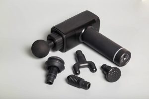
Industrial Equipment – Jigs, Fixtures, and Replacement Parts
Production lines can’t afford long downtimes waiting for replacement tooling. MJF produces custom jigs, fixtures, and low-volume spare parts on demand, keeping manufacturing running smoothly. We’ve seen factories reduce downtime by 40% simply by printing critical fixtures instead of ordering them through traditional machining.
If you’re wondering whether MJF fits your industry, the key question is: Do you need functional parts quickly, in low to medium volumes, without heavy tooling investment? If the answer is yes, MJF is often the most cost-effective route.

MJF vs. Other Manufacturing Methods
When you’re choosing a manufacturing method, it’s rarely about which technology is “best” overall—it’s about which one fits your timeline, budget, and production goals. Here’s how MJF stacks up against some common alternatives:
MJF vs. SLS – Speed and Surface Quality
SLS has been around longer and is proven for industrial use. But it relies on lasers tracing every layer, which slows things down. With MJF, the entire layer fuses at once, so build times drop by 30–50% on average. We’ve also noticed that MJF parts come out with sharper edges and smoother surfaces, reducing post-processing time. If you’re under tight deadlines, MJF usually wins.

MJF vs. FDM – Strength and Accuracy
FDM is inexpensive and fine for rough prototypes, but it leaves visible layer lines and anisotropic strength (weaker across layers). MJF parts, by contrast, have near-isotropic mechanical properties—they handle mechanical loads better and look closer to final production quality. For functional prototypes or end-use parts, FDM often falls short where MJF excels.

MJF vs. Injection Molding – Volume and Cost Efficiency
Injection molding still dominates for high-volume production because of its low per-part cost once tooling is made. But tooling alone can cost tens of thousands of dollars and take months to deliver. For low to medium volumes (1–1,000 parts), MJF eliminates tooling entirely, giving you parts in days rather than weeks—at a fraction of the upfront cost.
Here’s a quick decision guide based on what we see in real projects:
| Factor | MJF | SLS | FDM | Injection Molding |
| Lead Time | Days | Days–Weeks | Days | Weeks–Months |
| Part Strength | High, isotropic | High, slightly anisotropic | Moderate | Very High |
| Surface Quality | Smooth, detailed | Good, needs finishing | Rough | Excellent |
| Volume Efficiency | Low–Medium (1–1,000 parts) | Low–Medium (1–500 parts) | Prototypes only | High (1,000+ parts) |
| Tooling Cost | None | None | None | High (but low per-part cost later) |
If you need fast turnaround, strong parts, and no tooling costs, MJF is hard to beat. But if your production volumes are high enough to justify tooling investment, injection molding eventually becomes more cost-efficient.
Cost Factors & ROI Considerations
If you’ve ever struggled to justify 3D printing costs to your management team, you’re not alone. We get this question from clients all the time: “When does MJF make financial sense compared to machining or injection molding?”
The answer comes down to a few key cost drivers:
Material Usage – Every Gram Counts
MJF uses polymer powder, and while unused powder can be recycled, fresh material still adds cost. We’ve seen projects save 10–15% simply by hollowing thick sections or consolidating multiple small parts into one build. Less material doesn’t just cut costs—it often reduces build time too.
Build Time – Height Matters
Unlike CNC machining, where complexity drives cost, in MJF the build height often decides the price. Taller parts mean more layers, which means longer print times. We advise clients to keep parts as flat as functionally possible—sometimes splitting a design into two interlocking halves reduces both cost and risk.
Post-Processing – More Than Cosmetic
Bead blasting is cheap and quick. Vapor smoothing or coatings add labor and turnaround time. Before selecting a finish, ask yourself: Do you really need a glossy, sealed surface for internal fixtures? Often, clients over-specify finishes and end up paying for aesthetics that don’t matter in the real application.
Labor and Setup – Batch Size Effects
Here’s where ROI gets interesting. MJF pricing isn’t linear. A single part absorbs all the setup cost, but in larger batches, that overhead spreads out, so the cost per part drops sharply.
We’ve plotted cost-per-part for clients like this:
- 1 part → Highest cost (all setup cost on one piece)
- 100 parts → 40–60% lower per-part cost
- 500 parts → Up to 80% savings compared to single parts
That’s why we often tell clients: if you have 50+ units, print them in one run rather than separate orders. The savings are real.

ROI Threshold – When to Switch to Molding
For low to medium volumes (1–1,000 parts), MJF typically beats injection molding because you avoid tooling costs altogether. Once volumes hit 2,000–5,000 units, the per-part cost of molding drops below MJF even after paying for tooling. Knowing this crossover point avoids expensive surprises later.
Common Challenges & Best Practices
Even with the speed and flexibility of MJF, we see some problems come up again and again—mostly because design teams forget that 3D printing isn’t magic. Parts can still warp, dimensions can drift, and costs can spiral if you’re not careful. Let’s talk about the ones that matter most:
Warping During Cooling: If walls are too thin or large flat sections cool unevenly, parts can warp. We’ve seen this in big enclosures where one corner lifts just enough to cause assembly headaches. The fix? Add ribs or break large surfaces into smaller sections. It strengthens the part and keeps the geometry stable without much extra material cost.
Dimensional Accuracy in Tight Fits: MJF is good—typically ±0.3 mm or ±0.3%—but if you’re designing press-fit parts or housings for electronics, that margin can be critical. Our engineers usually leave 0.1–0.2 mm extra clearance and then dial it in after the first print run. It’s faster and cheaper than rejecting an entire batch because it’s too tight.
Powder Removal in Internal Channels: Internal cavities look great in CAD but often trap powder in real life. We’ve seen clients drill out clogged channels after printing, which defeats the purpose of fast manufacturing. The best practice? Design escape holes at least 2 mm in diameter or split the part into two sections for easier cleaning.
Surface Finish Expectations: Some teams expect injection-mold-like surfaces straight off the printer. Reality check: MJF parts start with a matte, slightly grainy texture. If you need cosmetic quality, plan for dyeing or vapor smoothing in your timeline and budget. Surprises here cause more project delays than you’d think.
Cost Creep from Over-Specifying Parts: Not every jig or fixture needs aerospace-grade finishes or ultra-tight tolerances. We’ve helped companies cut costs by matching the print spec to the real-world use case instead of chasing perfection where it doesn’t matter.
In short, designing with MJF in mind upfront prevents most of these headaches. A short DFM review before you hit “print” often saves more time and money than any post-processing trick after the fact.
Conclusion
Multi Jet Fusion has changed how companies approach prototyping and low-volume production. Faster lead times, strong and accurate parts, and predictable costs—it’s a practical choice when speed and quality matter.
If you want to see how MJF fits your next project, upload your CAD files for a quick cost analysis or talk to our engineers about design optimization. The sooner you start, the faster you move from idea to production.
FAQs
What is the maximum part size for MJF printing?
The maximum build size for most HP Multi Jet Fusion printers, such as the HP Jet Fusion 4200/5200 series, is 380 x 284 x 380 mm (15 x 11.2 x 15 in). If your part is larger than this, there are two common solutions:
- Split the design into multiple sections with interlocking features so it can be printed in smaller pieces and assembled later.
- Work with a manufacturing partner who can recommend alternate technologies or hybrid approaches for oversized components.
Staying within the build size not only avoids extra assembly work but also helps keep print times and costs predictable.
How accurate are MJF parts in terms of dimensions and tolerances?
MJF parts typically achieve ±0.3% dimensional accuracy with a minimum of ±0.3 mm. For most prototypes and low-volume production parts, this level of precision is enough to meet functional and assembly requirements.
However, keep in mind a few practical points:
- Post-processing effects: Bead blasting or vapor smoothing can slightly alter dimensions, so we recommend leaving small clearance gaps for tight fits.
- Part geometry and size: Larger parts or thin walls may show more variation due to thermal stress during cooling.
- Design optimization: A quick design-for-manufacturing (DFM) review before production often prevents tolerance issues and reduces rework.
For applications requiring extremely tight tolerances, secondary operations like CNC machining on critical features can bring parts within ±0.1 mm if needed.
What materials are available for MJF, and how do they differ?
MJF primarily uses polymer powders, with each material offering unique properties for different applications. The most common options include:
- PA 12: The go-to material for functional prototypes and end-use parts. It balances strength, stiffness, and cost, making it suitable for housings, fixtures, and general-purpose components.
- PA 11: More flexible and impact-resistant than PA 12. Often chosen for automotive clips, sports gear, and parts needing ductility under load.
- PA 12 Glass Bead (PA 12 GB): Reinforced with glass beads for added stiffness and dimensional stability. Ideal for tooling, jigs, and parts exposed to mechanical stress.
- TPU (Thermoplastic Polyurethane): Provides rubber-like elasticity for gaskets, seals, and cushioning parts where flexibility and energy absorption are critical.
- PP (Polypropylene): Lightweight with excellent chemical resistance, suitable for fluid-handling components and applications needing low density.
Choosing the right material depends on mechanical requirements, environmental exposure, and cost targets. Many manufacturers test small batches in two materials before committing to full production to validate performance and cost.
Can MJF be used for end-use production parts, or only for prototyping?
MJF started as a rapid prototyping technology, but it is now widely used for end-use production parts in low to medium volumes. Its combination of strength, dimensional accuracy, and repeatability makes it suitable for functional components—not just visual models.
Common examples of end-use applications include:
- Automotive: Custom brackets, HVAC components, interior fittings
- Medical: Surgical guides, orthotic devices, lab equipment parts
- Consumer products: Electronic housings, custom enclosures, sporting goods
The key factor is production volume. For runs under 1,000 units, MJF often outperforms injection molding by eliminating tooling costs and cutting lead times from weeks to days. For very high volumes, injection molding remains more cost-effective.


