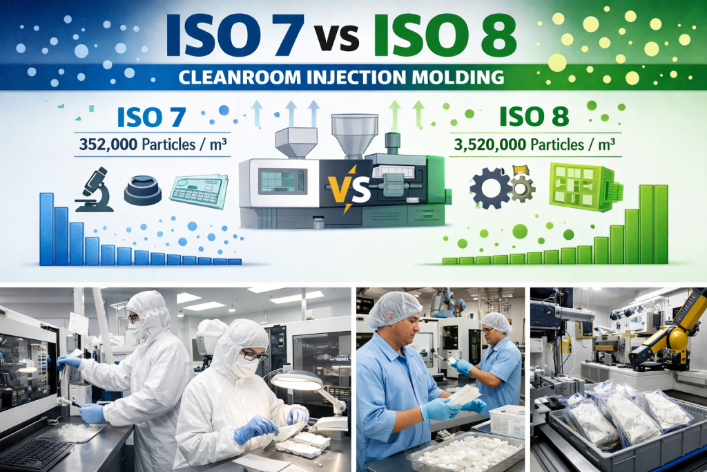
Selecting the appropriate cleanroom classification requires a rigorous analysis of particle sensitivity versus total operational expenditure (OpEx), specifically when evaluating ISO 7 vs ISO 8 for injection molding.
While ISO Class 7 provides a tenfold increase in airborne cleanliness, this overhead is typically justified only for critical geometries, such as optical surfaces or complex fluidic paths.
For most medical housings and structural components, the higher cost of an ISO 7 environment is often unnecessary. In these cases, an ISO Class 8 environment—when integrated with high-stability process controls—achieves the most effective technical and economic balance without the excessive burden of high-frequency air changes and strict gowning protocols.
Key Differences in Particle Control & Environment
The practical difference between ISO Class 7 and ISO Class 8 lies in the concentration of airborne particles and how that impacts your parts after the mold opens.
Particle Fallout and Deposition Rates
ISO Class 7 is 10 times cleaner than ISO Class 8.
- ISO 8: Allows up to 3,520,000 particles ($\ge 0.5 \mu m$) per cubic meter.
- ISO 7: Limits particles to 352,000 per cubic meter.
In injection molding, the room environment only matters after the mold opens. ISO 7 reduces the “fallout rate,” meaning fewer particles settle on the part during pick-off, inspection, and transfer.
Sensitivity to Exposure Time
Both classes can produce “clean” parts if they are sealed quickly. However, ISO Class 7 provides a larger safety margin. If your process requires detailed manual inspection, complex assembly, or temporary staging before bagging, the cleaner background of ISO 7 prevents particle accumulation over those longer durations.
Operational Complexity and Cost Implications
Selecting ISO 7 vs ISO 8 for cleanroom injection molding involves a significant shift in long-term Operational Expenditure (OpEx). ISO Class 7 is not merely a one-time infrastructure investment; it represents a permanent increase in the cost of goods sold (COGS).
HVAC and Air Change Requirements (ACPH)
The primary driver of cleanroom cost is the Air Changes Per Hour (ACPH).
- ISO 8: Typically requires 15–25 air changes per hour.
- ISO 7: Requires 30–60 air changes per hour.
This doubling of airflow requires disproportionately more powerful HVAC systems and results in higher electricity consumption. Furthermore, the increased load necessitates more frequent HEPA filter replacements to maintain the required pressure differentials and particle limits.
Gowning Protocols and Personnel Friction
The human element remains the primary source of contamination in any controlled environment.
- ISO Class 8: Generally allows for standard lab coats, hairnets, and shoe covers, facilitating ease of movement and lower consumable costs.
- ISO Class 7: Usually mandates full coveralls (bunny suits), masks, and gloves.
Strict gowning increases the time it takes for staff to enter/exit and can reduce operator dexterity and comfort, potentially impacting manual assembly yields.
Given the substantial overhead and operational friction associated with ISO Class 7, this investment is only rational if airborne particles are the primary driver of product failure. Identifying the following myths is critical to determining whether a cleaner room—or a more stable process—is the true requirement.
Common Myths: What a Cleaner Room Won’t Fix
A common mistake is “upgrading” the room to solve quality issues that aren’t caused by the air.
Mistake 1: Treating Process Defects as Room Contamination
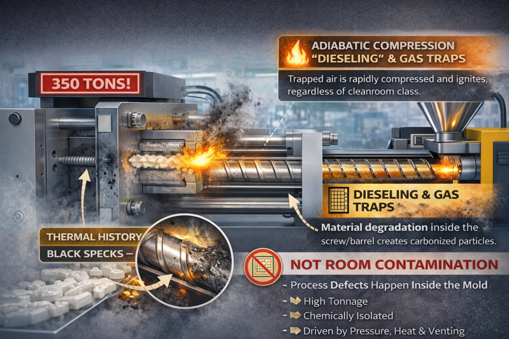
Burn marks, dieseling, and gas traps happen inside the closed mold. If you see black specks caused by material degradation or poor venting, an ISO 7 room will not fix them.
While a cleaner environment reduces airborne particulates, it has no impact on the physics of the injection cycle. Because the mold is clamped under high tonnage, it functions as an isolated system during the critical formation of the part. These specific defects are usually the result of:
- Adiabatic Compression: The “dieseling” effect occurs when trapped air is compressed so rapidly that it ignites, regardless of the surrounding air’s ISO classification.
- Thermal History: Black specks often originate from material carbonization within the screw or barrel, representing a chemical degradation issue rather than a physical contamination problem.
In these scenarios, the solution lies in optimized venting and process stability, not in the costly over-specification of the cleanroom environment.
Mistake 2: Ignoring Process-Generated Debris
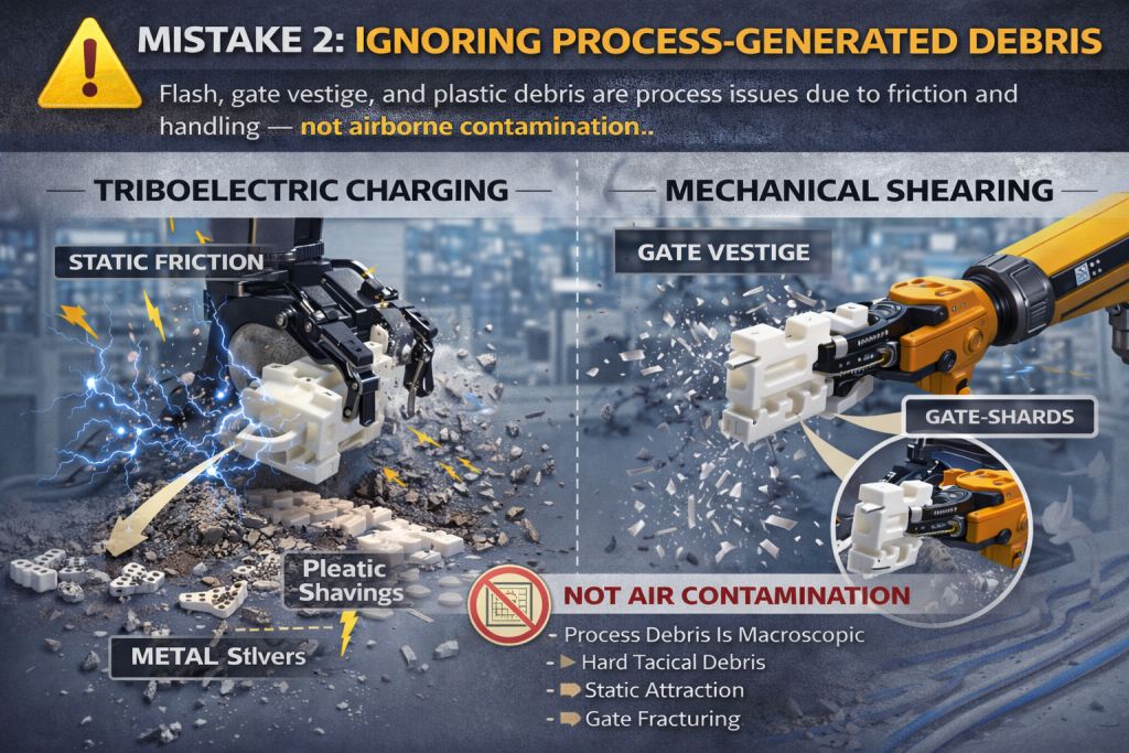
If your parts have flash, gate vestige, or trimming debris, the “contamination” is coming from the tool or the handling process itself. Plastic-on-plastic friction and static electricity often attract more debris than airborne fallout.
In high-volume injection molding, the primary particulate threat is often macroscopic rather than airborne. While an ISO 7 cleanroom focuses on filtering particles at the $0.5 \mu m$ scale, process-generated debris is often several orders of magnitude larger, making it immune to standard air-change dynamics. The depth of this issue lies in two areas:
- Triboelectric Charging: Injection molded polymers are excellent insulators. The friction of parts sliding down chutes or rubbing against one another generates a high static charge. This creates a localized electromagnetic field that aggressively attracts heavy, non-airborne debris (like metal slivers or plastic shavings) from the floor or equipment, rendering the ambient air’s ISO classification secondary.
- Mechanical Shearing: Contamination often originates at the gate. When a robot or operator separates a part from the runner, the mechanical shearing of the polymer creates “micro-shards” of plastic. These particles are born at the part surface and are often trapped by static before the cleanroom’s laminar flow can evacuate them.
In these cases, the solution is not a cleaner room, but ionizers, specialized de-gating tools, and low-friction handling systems.
Mistake 3: Over-specifying to Compensate for Instability

An ISO 7 cleanroom is designed to filter airborne particulates, but it cannot intervene in failures that originate within the machine’s mechanical or chemical systems. Because the injection molding cycle occurs in a sealed environment, air cleanliness is irrelevant to the following defects:
Internal Chemical Failures (Hydrolysis)
For hygroscopic resins, moisture during the melt phase triggers hydrolysis—a chemical reaction that breaks the polymer chains (chain scission). This causes “splay” or structural brittleness. Since this degradation occurs entirely within the sealed barrel and screw, it is physically isolated from the cleanroom’s air-handling system.
Melt Stream Contamination (Carbonization)
Black specks are typically the result of thermal carbonization due to excessive residence time or dead spots in the barrel. These are “intrinsic contaminants” generated inside the melt itself. Because these particles are born downstream of the HEPA filters and injected directly into the mold, an ISO 7 environment has no path to intercept them.
Mechanical Seal Failures (Tooling Wear)
Flash and plastic slivers are caused by mechanical seal failure at the mold’s parting line. When injection pressure exceeds the clamping force or the tool steel is worn, the melt escapes the cavity. These macro-particles are generated at the moment of part formation; they are a tooling maintenance issue that no level of atmospheric filtration can resolve.
Selection Strategy: How to Choose for Your Project
The decision between ISO 7 and ISO 8 should not be based on a generic “medical” label, but on a quantitative assessment of part exposure and functional sensitivity.
When to Specify ISO Class 7: High-Sensitivity Interdependency
ISO 7 is only a technical requirement when a part’s functional integrity is compromised by particles at the $0.5 \mu m$ scale. This typically applies to:
- Micro-Sealing Surfaces: Where a single microscopic particle on a gasket seat or fluid-path feature can lead to catastrophic seal failure or contamination.
- Optical Integration: Lenses or high-gloss display surfaces where airborne fallout creates non-correctable cosmetic rejects.
- Extended Exposure Windows: In scenarios where post-mold inspection or secondary manual assembly requires the part to remain exposed to ambient air for more than a few seconds.
When to Specify ISO Class 8: High-Stability Process Logic
For the majority of medical housings and structural components, ISO 8 provides the optimal balance. This classification is sufficient when:
- “Bag-and-Seal” Automation: The production cell is designed for immediate packaging, where the part’s atmospheric exposure is measured in milliseconds rather than minutes.
- Macro-Scale Functional Requirements: The part’s assembly or performance is not impacted by particles at the sub-micron level.
- Process-Driven Quality: When the focus is on maintaining a stable, automated handling system that mitigates contamination through speed and mechanical isolation, rather than through massive air-change volumes.
Summary: Cleanroom Class Is a Tool, Not the Goal
Stable yield comes from matching the cleanroom class to the actual risk. A higher class does not guarantee better parts—it only guarantees higher costs. Focus on process stability and handling discipline first, then select the lowest ISO class that reliably controls your particle risk.
Would you like a technical review of your cleanroom requirements?
Contact our Engineering Team for a DFM (Design for Manufacturing) analysis to determine the most cost-effective ISO classification for your next injection molding project.