CMM measurement is a dimensional inspection method that uses a coordinate measuring machine to record points on a physical part in the X, Y, and Z directions. Inspection software converts those coordinates into measurable geometry such as planes, circles, cylinders, distances, angles, profiles, feature locations, and GD&T results. In purchasing and quality conversations, “CMM measurement” usually means either measuring a part on a CMM or receiving a dimensional inspection report generated from that measurement.

Key Takeaways
- A CMM measures coordinates on a part surface; the software uses those points to calculate and evaluate geometry.
- CMM inspection is especially useful for complex feature relationships, GD&T, multi-axis or multi-setup parts, first-article verification, and traceable dimensional reports.
- A CMM is not automatically the best tool for every dimension. Calipers, micrometers, gauges, and optical systems can be faster or more appropriate for simple or method-specific checks.
- A useful CMM report must show more than PASS/FAIL. It should identify the nominal value, tolerance, measured value, deviation, datum/alignment basis, part revision, sample, and inspection traceability.
- Measurement capability depends on the complete method: machine, probe, stylus, fixture, environment, alignment, point strategy, software rules, and measurement uncertainty.
What Does a CMM Actually Measure?
A CMM does not directly “see” a finished dimension. It collects discrete points or scanned coordinates from the part surface. The software then fits those data to nominal or constructed geometry and compares the result with the drawing or CAD definition.
Depending on the probe, program, and feature accessibility, a CMM can evaluate:
- Linear dimensions, diameters, radii, angles, and depths
- Planes, lines, circles, cylinders, cones, spheres, and slots
- Feature locations, hole patterns, centerlines, and intersections
- Flatness, straightness, circularity, and cylindricity
- Parallelism, perpendicularity, angularity, and orientation
- Position, runout, profile, and other GD&T characteristics when the datum and evaluation rules are correctly defined
- Distances between measured or constructed features
- Deviation from nominal CAD surfaces using point-based or color-map comparison
The measurement strategy matters. A diameter calculated from a small number of touch points can differ from a dense scan of the same feature. Point distribution, fitting method, filtering, probe direction, surface condition, and the inspection objective can all affect the reported value.

How Does CMM Measurement Work?
Most CMM systems combine a structure that moves in three axes, a sensor or probe that detects the part surface, scales or encoders that record position, and software that constructs and evaluates geometric features.
1. Establish the machine coordinate system
The CMM operates within its own calibrated X, Y, and Z coordinate system. The inspection setup must relate the workpiece to that machine system.
2. Qualify the probe
The stylus and probe orientations are qualified against a calibrated reference so the software can account for the effective stylus geometry. Qualification does not eliminate risks from loose styli, collisions, excessive extensions, temperature change, or unsuitable probing directions.
3. Align the part to its datums
The program measures the features that establish the part coordinate system. The alignment should follow the drawing datum reference frame or another approved inspection strategy rather than an arbitrary surface that is merely convenient to probe.
4. Collect points or scan surfaces
Touch-trigger probes collect discrete contact points, scanning probes collect dense surface data, and suitable optical sensors can capture points or edges without contact.
5. Construct and evaluate features
The software fits the measured data to circles, planes, cylinders, profiles, centerlines, intersections, and other features, then compares them with nominal dimensions and tolerance requirements.
6. Generate and review the report
The report typically shows nominal values, measured values, deviations, tolerance limits, and pass/fail status. It should also preserve enough part, program, datum, and inspection information to make the result traceable and understandable.

When Do You Need CMM Inspection?
CMM inspection becomes valuable when the engineering question depends on relationships between features, not just one local size measurement.
Typical use cases include:
- First-article inspection after a new machining program, setup, tool, mold, or engineering change
- True position, profile, perpendicularity, parallelism, runout, or other GD&T requirements referenced to functional datums
- Hole patterns, compound angles, deep bores, complex milled surfaces, and features created across multiple setups
- Multi-axis parts where the same feature relationship is difficult to establish with calipers or micrometers
- Tooling and mold validation where measured deviation is used to support correction decisions
- Final inspection or supplier approval when a traceable dimensional report is required
- Process troubleshooting or capability work where repeated dimensional data are needed to distinguish setup or process trends from one-off checks
Not every drawing dimension requires CMM inspection. Critical-to-quality features should be identified first. Simple lengths, diameters, or thicknesses may be faster and equally valid with micrometers, gauges, or other dedicated methods when those tools are capable for the tolerance and feature.
Types of CMMs and Measurement Systems
The best system depends on part size, tolerance, accessibility, production environment, surface condition, throughput, and whether the part can be moved into a controlled metrology area.
Probe choice also matters:
- Touch-trigger probes are well suited to defined features such as holes, bosses, planes, pockets, and prismatic geometry.
- Tactile scanning probes collect many points continuously and can improve form or profile evaluation, but scan speed, filtering, stylus behavior, cleanliness, and coverage still require control.
- Optical sensors measure without contact and can be useful for small, flexible, delicate, or difficult-to-touch features. Reflective, transparent, dark, textured, or poorly defined surfaces may need special methods or another instrument.
CMM Measurement and GD&T
GD&T defines how feature form, orientation, and location relate to functional datums. A CMM can calculate many GD&T characteristics efficiently, but only when the correct datum reference frame and evaluation rules are used.
Common sources of error include:
| System type | Typical strength | Main limitation or question |
|---|---|---|
| Bridge CMM | General precision inspection of small and medium parts; repeatable automated programs | Requires suitable working volume, fixturing, access, and environmental control |
| Gantry CMM | Large or heavy components with access around the part | Greater installation, foundation, environment, and programming demands |
| Portable articulated arm | Large parts, tooling, assemblies, and on-site measurement | Capability is strongly influenced by operator technique, arm posture, environment, and access |
| Vision / optical or multisensor system | Small, flexible, delicate, edge-based, or dense-surface features | Reflectivity, focus, edge definition, transparency, and line-of-sight can limit reliability |
- Using a convenient best-fit alignment instead of the drawing datums
- Measuring only part of a datum feature without an approved reason
- Evaluating profile without confirming the tolerance disposition and datum structure
- Ignoring material-boundary or modifier requirements when they apply
- Treating position as a simple plus/minus center-distance check
- Comparing scan color maps that were created with different alignments, filters, or color scales
Color maps can be useful for diagnosing warpage, shape, tooling correction, or surface deviation, but the report should state the alignment, units, scale, filtering, coverage, and whether the map is diagnostic or an acceptance record.
How Accurate Is CMM Measurement?
There is no single accuracy value that applies to every CMM or every feature. Measurement capability depends on the machine specification, measured length, probe and stylus, temperature, fixture, part condition, feature access, point strategy, software evaluation, and the uncertainty of the complete method.
| Term | Practical meaning |
|---|---|
| Resolution | The smallest displayed or encoded increment; it does not by itself prove measurement accuracy |
| Repeatability | How closely repeated results agree under defined conditions |
| Accuracy | How close results are expected to be to an accepted reference under specified conditions |
| Maximum permissible error (MPE) | A stated performance limit under defined verification conditions |
| Measurement uncertainty | A quantified range associated with a result that considers relevant sources of doubt |
| Calibration | Comparison with traceable standards to establish performance and corrections under defined conditions |
For tight-tolerance decisions, the measurement process should have substantially smaller uncertainty than the tolerance being evaluated. Ratios such as 10:1 or 4:1 are often discussed as planning rules, but they are not universal acceptance rules; the required decision rule should come from the project, customer requirement, quality system, risk, and applicable standard.
CMM vs. Calipers, Micrometers, and Optical Measurement
The right question is not “Is a CMM better?” but “Which measurement method is capable and efficient for this feature?” The most effective inspection plans often combine methods.
| Method | Best suited to | Advantage | Limitation |
|---|---|---|---|
| Caliper | General outside, inside, depth, and step checks | Fast, portable, economical | Operator-sensitive; limited for tight tolerances and complex GD&T |
| Micrometer | Controlled diameter, thickness, or length measurements | Stable contact geometry and high resolution for suitable features | Limited feature types and local measurement only |
| Fixed CMM | Complex 3D relationships, GD&T, repeat programs, traceable reports | Flexible geometry evaluation and digital reporting | Higher programming, fixturing, cycle-time, and environment demands |
| Vision / optical system | Small, delicate, flexible, edge-based, or dense-surface features | Non-contact and potentially high data density | Surface, focus, transparency, reflectivity, and edge behavior can affect results |
| Functional gauge | High-volume pass/fail verification of a defined fit or function | Fast and directly related to function when designed correctly | Limited variable data and requires dedicated tooling |

For example, a CMM may verify hole position and profile, a micrometer may check a shaft diameter, and a functional gauge may confirm assembly. Using the most complex instrument for every characteristic can increase inspection time without improving the decision.
How to Read a CMM Inspection Report
A CMM report should help the buyer answer four questions: what was measured, which requirement was used, what result was obtained, and whether the measurement is traceable to the correct part and inspection method.

CMM Inspection for CNC Machined Parts
For precision CNC machining services, CMM inspection is most useful when the drawing contains feature relationships that are difficult to verify from one local measurement. This is common with true-position requirements, perpendicular bores, compound angles, profiles, deep pockets, 5-axis features, and geometry created across multiple setups. A CMM program can support:
- First-article verification after programming and setup
- Datum transfer checks across multiple machining operations
- Hole-pattern and threaded-feature location checks
- Profile comparison for complex milled surfaces
- Process-offset decisions based on measured trends
- Final dimensional reports for critical features

Inspection access should be reviewed during DFM rather than after machining. Deep recesses, obstructed bores, small features, long probe extensions, or insufficient datum access can make an apparently straightforward tolerance difficult to verify with adequate confidence.
CMM Inspection for Mold Components and Injection-Molded Parts
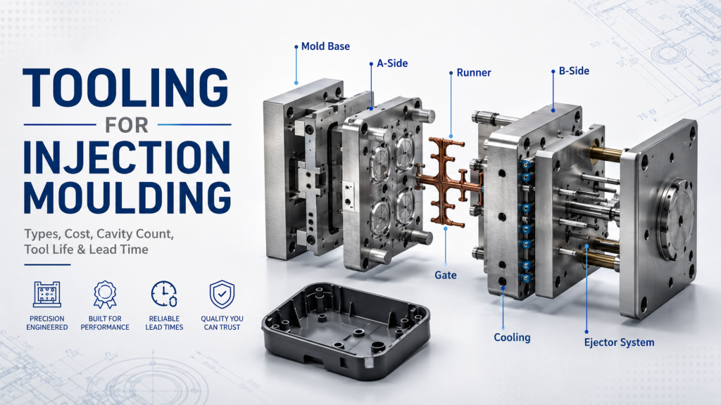
Mold components can require the same datum-controlled dimensional verification as other precision machined parts, especially when inserts, shutoffs, slides, cavity/core relationships, or critical interfaces must be checked before assembly. For molded plastic parts, the measurement plan also has to account for the part condition.
- Material grade, conditioning, moisture, and relevant part state
- Cavity identification and molding process revision
- Time between molding and measurement when dimensional stability is relevant
- Free-state, restrained-state, or functional-fixture condition
- Datum stability on drafted, textured, parting-line, or flexible surfaces
- Critical assembly features rather than every available dimension
CMM data can support tooling correction and process troubleshooting, but a correction decision should not be based on one scan or one sample without a controlled alignment, repeatable support condition, and agreed acceptance method.
Common CMM Measurement Mistakes
| Mistake | Why it creates risk | Better approach |
|---|---|---|
| Inspecting the wrong revision | PASS/FAIL is compared with obsolete requirements | Lock the drawing, CAD, program, and report revisions before measurement |
| Using convenient rather than functional datums | The coordinate system may not represent assembly | Follow the approved datum reference frame and document any deviation |
| Too few or poorly distributed points | Fitted geometry can miss important form variation | Match point strategy to feature size, form risk, and the inspection decision |
| Ignoring burrs, dirt, roughness, or coating condition | The probe can measure contamination or local surface peaks | Define the accepted part condition and clean without altering the part |
| Over-clamping flexible parts | The fixture can create a false pass or false fail | Specify free-state or restrained-state measurement and control the support |
| Treating resolution as accuracy | A fine display can create false confidence | Review the complete machine/probe capability, uncertainty, environment, and method |
| Blindly accepting software status | Incorrect mapping or settings can still produce a green result | Review alignment, units, fitting, filtering, tolerance rules, and feature mapping |
| Leaving inspection planning until production release | Probe access and datum problems appear too late | Review measurement feasibility during DFM and drawing release |
How to Specify CMM Inspection in an RFQ
To confirm measurement feasibility and quote the inspection effort correctly, provide the supplier with:
- Controlled 3D CAD and 2D drawing revisions
- Material, finish, coating, and relevant inspection condition
- General tolerances and the applicable GD&T standard
- Critical-to-quality (CTQ) or ballooned feature list
- Datum and fixturing requirements
- Sample quantity and sampling frequency
- First-article, production, final-inspection, or capability-study requirements
- Required report format and language
- Any MSA, gauge R&R, measurement uncertainty, guard-band, or decision-rule requirements
- Traceability, record-retention, and approval requirements
For prototypes, separate dimensions used for design learning from characteristics used for formal acceptance. This helps the supplier choose an inspection plan that is technically appropriate without adding unnecessary reporting cost.
Questions to Ask a Manufacturing Supplier About CMM Capability
- Which drawing features will be measured on the CMM, and which will use other methods?
- What CMM, probe, stylus configuration, and working volume are proposed for the part?
- Can the part and fixture fit without inaccessible features or excessive probe extensions?
- How will the datum reference frame be established and verified?
- How will flexible, coated, textured, or temperature-sensitive parts be supported and conditioned?
- How is measurement capability evaluated relative to the tightest required tolerance?
- What report format, sample identification, revision control, and traceability will be supplied?
- What is the review process when manual and CMM results disagree?
A supplier having a CMM is only the starting point. Measurement capability depends on whether the complete inspection method is suitable for the actual feature, tolerance, part condition, and reporting requirement.
Frequently Asked Questions
What does CMM stand for?
CMM stands for coordinate measuring machine. It records points on a physical object in a coordinate system and uses those points to calculate and evaluate geometric features.
Is “CMM measurement” the correct term?
It is widely understood, although the phrase is somewhat repetitive because the final M already means machine. In practice, buyers use it to mean CMM inspection, coordinate measurement, or a dimensional report generated by a coordinate measuring machine.
Can a CMM measure surface roughness?
A conventional dimensional CMM probe is not automatically a surface-roughness instrument. Roughness parameters require an appropriate sensor or dedicated instrument, evaluation method, filter/cutoff, direction, and applicable standard.
Can a CMM measure threads?
A CMM can measure some accessible thread-related geometry or locate threaded features, but complete thread acceptance often requires dedicated thread gauges, optical methods, specialized software, or another method matched to the thread requirement.
Is CMM inspection better than a caliper?
It is better suited to many complex 3D relationships and GD&T characteristics, but it is not the best tool for every dimension. Calipers, micrometers, gauges, or optical systems may be faster and more appropriate for suitable features.
Do all parts need a full CMM report?
No. The report scope should reflect project risk, drawing requirements, production stage, and buyer needs. A full first-article report may be appropriate for initial approval, while controlled CTQ sampling may be more useful in stable production.
What files are needed for a CMM quotation?
Provide the controlled CAD model, toleranced drawing, material and finish, CTQ list, datum requirements, sample quantity, report format, and any applicable customer-specific or quality-system requirements.
Conclusion: CMM Measurement Is Only as Good as the Inspection Plan
CMM measurement turns physical surface points into dimensional and geometric evidence. Its real value comes from the complete inspection chain: the correct drawing revision, functional datums, capable equipment, suitable probe and fixture, controlled part condition, appropriate evaluation rules, and a traceable report.
If you are sourcing high-tolerance CNC or mold components, define the critical features and reporting requirements before production rather than treating “CMM inspection” as an undefined checkbox. Send the CAD model, drawing, datum scheme, tolerances, material, quantity, and required report format so manufacturing and measurement feasibility can be reviewed together before quotation.
For machining capability and project review, see Kemal’s CNC machining capabilities and submit your drawings together with the critical dimensions, datum requirements, and inspection-report expectations.