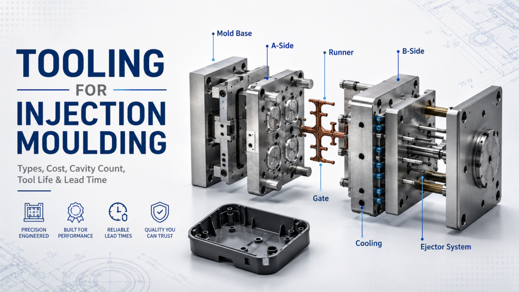
Tooling for injection moulding is the mold system that turns a 3D CAD design into repeatable plastic parts with the required dimensions, surface quality, and consistency. It typically includes the core, cavity, runners, gates, cooling channels, and ejection system, making the tooling a critical link between product design and stable production.
Because injection mold tooling is often one of the largest upfront investments in plastic product development, poor choices in mold material, cavity layout, gating, cooling, or part geometry can increase cost, delay production, and shorten mold life. This guide explains how to select the right tooling strategy based on production volume, material, part complexity, budget, and lifecycle requirements before moving into DFM, mold design, and manufacturing.
Section 1: Core Architecture of an Injection Mould Tool
An injection mould tool is a coordinated system rather than a single block of metal. Its core functions are to form the part geometry, deliver molten resin into the cavity, remove heat at a controlled rate, release the molded part, and manage features that cannot be formed with a simple opening direction. The mold architecture should therefore be selected around part geometry, production volume, resin behavior, surface requirements, automation needs, and maintenance expectations.
 Two-Plate vs. Three-Plate Injection Moulds
 Two-Plate vs. Three-Plate Injection Moulds
A two-plate mold separates at one main parting line between the core and cavity plates. It is the simpler and more widely used architecture because it requires fewer moving sections and is generally easier to manufacture, operate, and maintain. It is often suitable when the gate can be positioned at or near the main parting line, or when a hot-runner system feeds the cavity directly.
A three-plate mold adds an intermediate plate and a second separation plane. This provides more flexibility for pinpoint gating and can allow automatic separation of the cold runner from the molded part. The trade-off is greater mold height, more motion during opening, and additional alignment and maintenance requirements.
Selection rule: Use a two-plate architecture when the required gating and ejection can be achieved without the extra separation plane. Consider a three-plate design when gate location or automatic runner separation justifies the additional tooling complexity.
Core and Cavity: Where the Part Geometry Is Formed
The core and cavity create the primary molding surfaces. The cavity generally forms the external surfaces of the part, while the core commonly forms internal features such as recesses, ribs, bosses, and hollow sections. The exact division depends on parting-line strategy, shrinkage direction, ejection, draft, and cosmetic requirements.
Core-and-cavity design influences flash location, dimensional control, polishing access, venting, cooling, and how strongly the part grips one mold half after shrinkage. A practical objective is to keep the molded part on the side from which it can be ejected without damaging critical or cosmetic features.
Feeding and Gating System: Sprue, Runner, and Gate
The feeding system controls how molten polymer travels from the machine nozzle into the cavity. In a conventional cold-runner mold, the sprue carries material into the runner network and the runner distributes it to one or more gates. The gate is the final restriction before the cavity and therefore has a direct effect on filling, packing, weld-line location, gate vestige, shear, and automatic degating.
| Gate Type | Where It Fits | Main Trade-Off |
| Edge gate | General parts where the gate can enter at the parting line | Simple to machine and adjust, but usually requires trimming and leaves a visible vestige. |
| Pinpoint gate | Parts requiring a small gate mark or gating away from the main edge | Can support automatic separation in suitable tooling, but the smaller flow area must match resin and fill requirements. |
| Submarine / tunnel gate | Automatic degating below the parting line | Reduces manual trimming but requires sufficient geometry and mold space for the angled gate path. |
| Hot runner | Multi-cavity, high material-use, or direct-gating applications | Reduces or eliminates cold-runner scrap but adds heaters, controls, start-up considerations, maintenance, and spare-part requirements. |
Cooling System: Cycle Time and Warpage Control
Cooling design is one of the main factors controlling cycle time and dimensional stability. Channels must remove heat without creating large temperature differences between thick and thin areas of the part. Uneven cooling can contribute to warpage, sink, dimensional drift, gloss differences, or longer stabilization time.
Cooling performance depends on channel location, mold geometry, mold material, resin, coolant temperature and flow, pressure drop, and access for cleaning. Deep cores and localized thick sections often require additional attention because they can retain heat longer than surrounding features.
Ejection System: Removing the Part Without Damage
Ejection begins only after the part has cooled enough to release without unacceptable deformation. Ejector pins apply force at selected points, stripper plates spread force over a larger contact area, and air assist can help break vacuum or reduce sticking in suitable geometries.
The ejection layout should be coordinated with draft, texture, shrinkage onto the core, rib and boss geometry, part stiffness, and cosmetic zones. If excessive force is required, the design team should first check whether draft, finish, packing, undercuts, or ejection distribution can be improved rather than simply increasing ejector force.
Side-Actions and Undercuts: Sliders, Lifters, and Unscrewing
Features that lock the part against the main mold-opening direction require a side-action or a design change. Sliders move laterally to release external undercuts or side holes. Lifters combine angled movement with ejection and are often used for internal undercuts. Threaded features may require an unscrewing mechanism when they cannot be stripped safely.
Every side-action adds components, machining, fitting, locking surfaces, wear points, and maintenance. During DFM, first determine whether the undercut is functionally necessary and whether a parting-line change, snap feature, separate component, or other geometry change can remove the mechanism.
Section 2: Injection Moulding Tooling Categories & Types
Injection moulding tooling should be selected according to the development stage, expected production volume, part geometry, resin, required validation, and expected tool life—not volume alone. Prototype, bridge, and production tooling describe manufacturing strategies, while single-cavity, multi-cavity, and family molds describe cavity configuration.
Prototype, Bridge, and Production Tooling
| Tooling Strategy | Primary Purpose | Typical Tooling Approach | Decision Logic |
| Prototype / rapid tooling | Design learning and production-material validation | 3D-printed inserts in limited cases, aluminum, or other rapidly manufactured tooling | Use when geometry or demand is still changing and the main goal is learning before a larger tooling commitment. |
| Bridge tooling | Pilot and low-volume production before long-term tooling is justified | Aluminum or pre-hardened / soft steel tooling depending on part and resin | Use when the design is reasonably stable but forecast, launch volume, or production location is not yet fully settled. |
| Production tooling | Repeatable, maintainable production over a longer program | More durable steel construction, replaceable wear areas, production-focused cooling and components | Use when demand is sustained and uptime, maintenance, interchangeability, cycle performance, and service life justify greater upfront engineering. |
Quantity ranges such as “under 100,” “100–10,000,” or “10,000+” can be useful as early planning references, but they are not universal industry boundaries. Abrasive fillers, corrosive additives, difficult shutoffs, side actions, part size, molding pressure, maintenance, and the required validation level can change the appropriate tooling strategy at the same volume.
Single-Cavity Tools
A single-cavity tool produces one part per molding cycle. It is often suitable for large components, lower production demand, early production, or projects where tool simplicity matters more than maximum machine output. The main trade-off is that one machine cycle produces only one finished component.
Multi-Cavity Tools
A multi-cavity tool produces several identical parts in one cycle. It can reduce machine time allocated to each part when demand is high enough, but the tooling investment and process-control burden increase. Runner balance, cavity-to-cavity cooling, shot size, clamp force, cavity identification, inspection, and maintenance all become more important as cavity count increases.
A higher cavity count is not automatically the lowest-cost solution. The right count depends on required output, forecast confidence, mold size, machine availability, cycle stability, downtime risk, and the cost of maintaining several cavities to the same condition.
Family Tools
A family mold produces different but related parts in the same cycle, such as two housing components used in one assembly. The advantage is consolidated tooling and synchronized output. The main challenge is that different part volumes, wall thicknesses, flow lengths, gate requirements, and cooling demands can make runner balancing and process optimization more difficult.
Use a family tool only when the parts can share a compatible molding window. If one cavity fills, packs, or cools very differently from another, separate tools may provide better process control even if the initial tooling investment is higher.
SPI / PLASTICS Mold Classes: A Tool-Life Reference
The PLASTICS Industry Association AR-101 guide is used in the moldmaking industry to describe mold classifications and approximate service-life expectations for quoting and purchasing. The classes are useful as a communication framework, but the cycle count is not a guarantee independent of resin, geometry, maintenance, and molding conditions.
| Mold Class | Approximate Life Reference | General Use |
| Class 101 | 1,000,000 cycles or more | Extremely high-production tooling with the most demanding construction and durability requirements. |
| Class 102 | Not exceeding 1,000,000 cycles | Medium- to high-production tooling. |
| Class 103 | Not exceeding 500,000 cycles | Medium-production tooling. |
| Class 104 | Not exceeding 100,000 cycles | Low-production tooling. |
| Class 105 | Not exceeding 500 cycles | Prototype-only tooling. |
Important: A mold cycle is not the same as one saleable part. A four-cavity tool can produce four parts in one cycle. Resin wear, moving mechanisms, cooling-water condition, maintenance, and process discipline also affect practical service life.
Section 3: Tooling Materials: Aluminum vs. Steel
The correct tooling material depends on the expected production life, resin abrasiveness or corrosiveness, part geometry, cosmetic finish, cooling requirements, repair strategy, and how much upfront tooling investment the program can justify. Aluminum favors machining speed and heat transfer; pre-hardened steels balance machinability and durability; hardened and corrosion-resistant tool steels are used when wear, corrosion, polish, or longer service life becomes more demanding.
Aluminum Tooling: Fast Machining and Strong Heat Transfer
High-strength aluminum alloys such as 7075-T6 and mold-specific aluminum plate such as QC-10 are used for prototype, bridge, and selected production applications. Aluminum machines more easily than most tool steels and has higher thermal conductivity, which can help remove heat where the mold layout and cooling strategy can take advantage of it.
The limitation is wear and damage resistance. Glass-filled resins, abrasive additives, repeated shutoff contact, thin steel conditions, or long production programs can make aluminum a poor economic choice even when the initial tool is quicker to machine.
Pre-Hardened Steel: P20 and NAK80
P20-type steels and NAK80 are commonly used when a tool requires more durability than aluminum but should remain relatively practical to machine and modify. These steels are supplied in a pre-hardened condition, so the main cavity blocks can often be machined without a separate through-hardening operation after rough machining.
NAK80 is also selected where polishability and dimensional stability are important. The actual grade and supplied hardness should be specified by material standard or mill documentation rather than relying only on a trade name.
Hardened and Corrosion-Resistant Tool Steels
H13, S7, and 420-type stainless mold steels serve different failure modes and should not be treated as interchangeable. H13 is commonly selected where toughness, wear, and thermal loading matter. S7 is a shock-resisting tool steel that can be useful for highly loaded components. 420-type stainless mold steels are selected where corrosion resistance, polishability, and wear resistance are important.
For glass-filled polymers, abrasion is a central concern. If the resin also contains corrosive additives or the production environment creates corrosion risk, a specialized corrosion- and wear-resistant mold steel may be more appropriate than a conventional steel. The material should be chosen around the dominant failure mechanism rather than the production-volume label alone.
Material Selection Comparison
| Factor | Aluminum | Pre-Hardened Steel | Hardened / Stainless Tool Steel |
| Tooling cost | Often lower for suitable, relatively simple tools because machining is faster. | Moderate; balances machining effort and durability. | Typically higher because material, heat treatment, finishing, fitting, or hard machining may increase work. |
| Tool-making lead time | Often shorter when geometry and inserts are suitable. | Moderate; pre-hardened condition can avoid a later hardening step. | Often longer where heat treatment and post-treatment finishing are required. |
| Thermal conductivity | High relative to conventional tool steels. | Lower than aluminum. | Generally lower than aluminum; varies significantly by grade. |
| Mold-life potential | Appropriate where wear demand and service-life requirement are limited or controlled. | Suitable for many general and medium-life production tools. | Favored for long-life, high-wear, corrosion-sensitive, or demanding production conditions. |
| Material compatibility | Works well with many unfilled resins when tool wear is manageable. | Suitable for many engineering resins; assess fillers and corrosive additives. | Select grade for abrasion, corrosion, polish, and mechanical load; often preferred for sustained filled-resin production. |
DFM / RFQ input: Before finalizing the mold material, provide the resin manufacturer and grade, filler or flame-retardant content, annual and lifetime volume, cosmetic finish, critical tolerances, expected maintenance conditions, and any required tool-life specification.
Section 4: The Tooling Manufacturing Process
A stable tooling project moves through controlled design, machining, finishing, assembly, and validation steps. The exact sequence varies by mold architecture, but the important point is to freeze key decisions before expensive machining and to keep revision control clear throughout the build.
1. 3D Tool Design and Assembly Modeling
The mold design converts the approved part geometry and DFM decisions into a complete assembly. The design should define core and cavity, parting line, inserts, cavity count, runner and gate, cooling, venting, ejection, slides or lifters, mold base, machine interfaces, purchased components, lifting points, and service access.
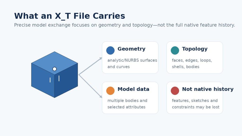
A 3D assembly alone is not enough for a controlled build. The toolmaker also needs released drawings or manufacturing data for critical components, steel specifications, heat-treatment requirements, and a documented revision so the shop is not machining against a changing CAD model.
2. Rough and Finish CNC Machining
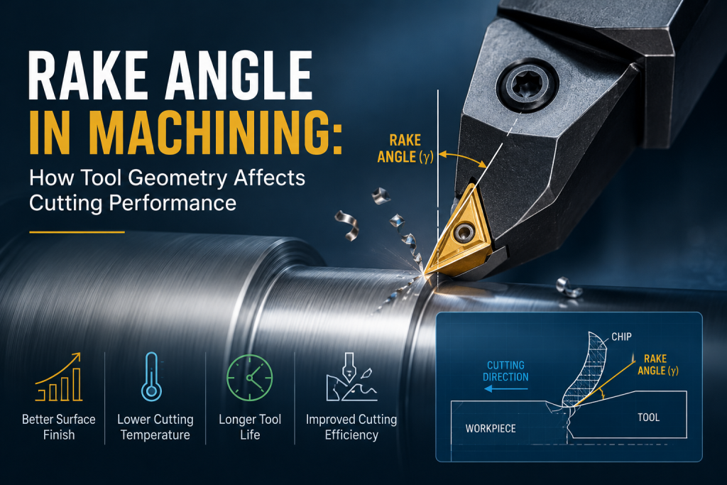
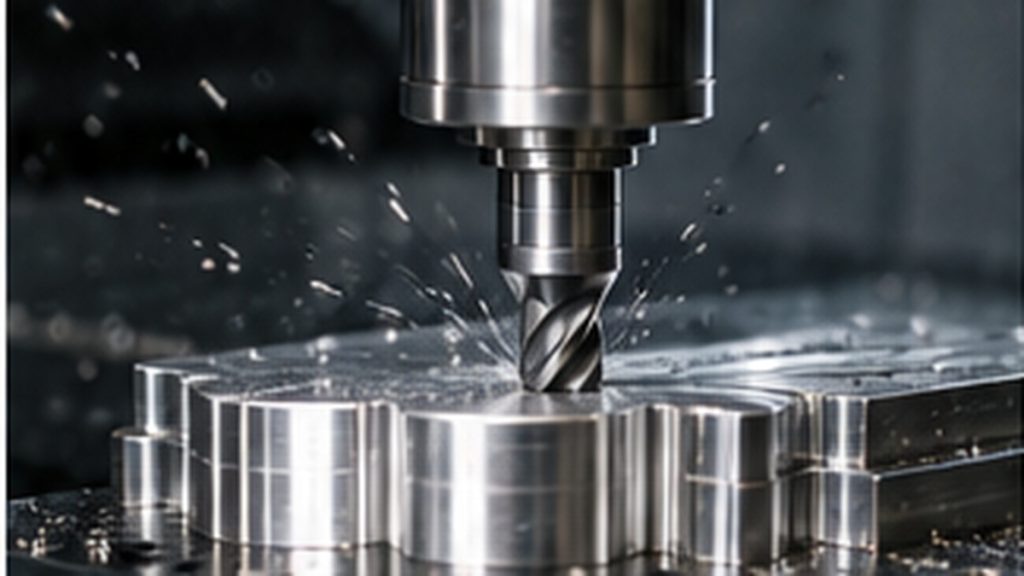
CNC milling is used to create mold plates, cores, cavities, inserts, electrodes, cooling features, and many alignment or mounting surfaces. Rough machining removes bulk material; finishing operations establish the surfaces and features required before EDM, heat treatment, grinding, polishing, or final fitting.
Machining strategy depends on steel condition, cavity depth, feature accessibility, surface requirements, and whether the component will be heat-treated later. Allowances for heat treatment, grinding, EDM, and hand fitting should be planned before the first cutting operation.
3. EDM and Wire EDM
Electrical discharge machining is used where geometry cannot be produced efficiently with conventional milling, particularly deep narrow cavities, sharp internal details, ribs, difficult corners, and hardened components. Wire EDM is used for through-features and precision profiles that can be accessed by the wire path.
EDM should be selected for geometry that justifies it rather than as a default. Electrode design, spark gap, surface condition, recast layer, polishing allowance, and dimensional inspection all affect the final result.
4. Surface Finishing, Polishing, and Texturing
Molding surfaces may be machined, polished, blasted, chemically textured, laser textured, or finished to a customer-approved visual standard. Commonly referenced SPI finish levels range from highly polished A-series finishes through progressively less polished B, C, and D finishes, while commercial texture systems such as Mold-Tech or VDI references may be specified for textured surfaces.
Surface finish is not purely cosmetic. Texture affects draft and ejection; polishing can expose steel defects; a deep texture can change how the part releases from the cavity. The drawing or approved appearance standard should define which surfaces are cosmetic and how they will be accepted.
5. Tool Assembly, Spotting, and Fitting
After individual components are finished, the mold is assembled and fitted. The toolmaker checks alignment, parting-line contact, shutoffs, slider and lifter travel, ejection, spring or hydraulic actions, cooling connections, hot-runner hardware, and mechanical interference.
Spotting and fitting are used to establish controlled contact where mold halves and shutoff surfaces must seal during injection. The goal is not simply that the mold can close; it must close repeatedly without flash-causing gaps, galling, binding, or unintended loading.
Release gate: Do not move to sampling until the approved mold revision, material condition, purchased components, cooling circuits, ejection motion, side actions, and safety/interlock functions have been checked against the design.
Section 5: Design for Manufacturability (DFM) & Tooling Optimization
DFM is most valuable before steel is released. It should identify geometry that increases tooling complexity, molding risk, or inspection difficulty and convert those issues into decisions that the designer, toolmaker, and buyer can approve before machining begins.
Draft Angle: Design for Reliable Release
Draft reduces sliding contact between the molded part and the core or cavity during ejection. Smooth straight-pull walls generally need positive draft, while textured surfaces often require additional draft because the texture increases mechanical engagement with the plastic.
The required angle depends on resin, depth, texture, surface finish, shrinkage, wall stiffness, and the direction in which the part is intended to stay after mold opening. Do not apply one universal angle to every wall; review deep ribs, bosses, shutoffs, and cosmetic walls separately.
Wall Thickness: Control Filling, Cooling, Sink, and Warpage
Uniform wall thickness generally produces a more stable molding condition because filling and cooling occur more consistently. Abrupt changes can create local hot spots, differential shrinkage, sink marks, void risk, hesitation, or warpage.
Where geometry requires a thicker local feature, use ribs, coring, gussets, or gradual transitions when function allows. The DFM review should identify thick intersections and explain whether the proposed geometry affects cooling, packing, or appearance rather than simply flagging wall thickness as “too thick.”
Undercut Removal: Reduce Side-Actions Before Cutting Steel
Undercuts often add sliders, lifters, collapsible cores, unscrewing systems, or manual inserts. These mechanisms add machining and fitting work and introduce wear surfaces, travel requirements, sensors or locks, and maintenance tasks.
The engineering question is whether the feature can be redesigned without changing function. A parting-line adjustment, snap geometry, open slot, separate insert, assembly change, or post-molding operation may remove a side-action. The cost effect must be quoted for the actual mold; a fixed percentage saving should not be assumed across unrelated designs.
Gate Location and Weld Lines: Design the Flow Path
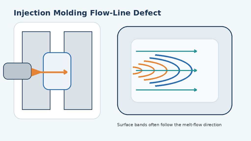
Gate location affects fill direction, pressure loss, packing, fiber orientation, weld-line position, air traps, gate vestige, and local appearance. A gate that is convenient for tool construction can still create a poor flow path for the part.
For difficult geometries, mold-flow analysis can be used to compare candidate gate locations, filling balance, air traps, weld-line position, pressure requirement, and cooling behavior. Simulation is a decision aid rather than proof of final part quality; the model inputs and assumptions must match the intended resin, mold, and process as closely as practical.
What a Useful DFM Report Should Show
- Controlled CAD revision and resin assumption.
- Proposed mold opening direction and parting line.
- Draft risks, deep features, and textured surfaces.
- Undercuts and proposed sliders, lifters, inserts, or redesign options.
- Gate location, expected gate mark, and runner concept.
- Likely weld lines, air traps, flow hesitation, and venting concerns.
- Ejector locations and cosmetic witness-mark risks.
- Wall-thickness transitions, sink/void risk, and cooling hot spots.
- Critical dimensions, datums, shrinkage assumptions, and inspection approach.
- Open questions that require customer approval before tool design or steel release.
For project-specific design review, see Kemal’s mold design services before releasing the tool for manufacture.
Section 6: Key Cost Factors in Injection Moulding Tooling
Tooling cost is the combined result of engineering, mold size, material, machining time, purchased systems, fitting, surface finishing, sampling, inspection, correction risk, and required documentation. The cheapest mold quote is not necessarily the lowest project cost if it omits validation, maintenance features, or production requirements.
Part Size and Complexity
Larger parts require larger cores, cavities, plates, and sometimes a larger mold base and molding machine. Complexity increases when the tool needs deep ribs, thin shutoffs, slides, lifters, unscrewing, inserts, difficult polishing, or multiple precision interfaces. The cost driver is the work required to create, fit, inspect, and maintain those features—not “complexity” as an abstract label.
Cavity Count
More cavities can increase production output per cycle and reduce machine time allocated to each component, but they also increase the amount of cavity machining, runner or hot-runner hardware, cooling design, balancing, inspection, and maintenance. The economic decision should compare tooling investment with the expected lifetime part demand and available molding capacity.
Tool Steel Selection
Higher-wear or corrosion-resistant steels can increase material and processing cost, especially when heat treatment, hard machining, grinding, polishing, or specialized welding is required. The material should be justified by resin, surface requirements, service life, and maintenance risk rather than selected solely to make the mold specification sound more robust.
Surface Texture and Polish Requirements
High-gloss surfaces and controlled textures add process steps and inspection requirements. Mirror-polished cavities demand suitable steel cleanliness and a controlled polishing sequence. Texturing requires attention to draft, texture depth, masking, repairability, and appearance matching across inserts or cavities.
Hot Runner vs. Cold Runner
A cold-runner system is mechanically simpler and may be easier to maintain or change, but each cycle can produce runner material that must be recycled, reprocessed, or scrapped according to material and quality requirements. A hot runner can reduce or eliminate cold-runner waste and can improve gating flexibility, but it adds manifolds, heaters, sensors, controllers, start-up procedures, spare parts, and maintenance risk.
A hot runner should be selected only after comparing resin sensitivity, color-change needs, gate cosmetics, runner scrap, cavity count, cycle behavior, maintenance capability, downtime risk, and the expected production life.
A Better Way to Compare Tooling Quotes
| Quote Item | What to Confirm |
| Tool scope | Mold base, cores/cavities, inserts, hot runner/controller, fixtures, gauges, spares, packaging, and documentation. |
| Tooling standard | Expected mold class or service-life basis, material specifications, hardness/heat treatment, and replaceable wear areas. |
| Cavity and runner concept | Cavity count, family or identical cavities, cold or hot runner, gate type, and any approved brands. |
| DFM and design | Who provides DFM, moldflow if required, design review, revisions, and customer approval gates. |
| Sampling and validation | T0/T1 scope, sample quantity, dimensional report, appearance review, capability or regulatory documentation if required. |
| Changes | How engineering changes after approval are quoted, documented, and scheduled. |
| Ownership and transfer | Ownership of mold, design data, electrodes, spare parts, maintenance records, and transfer package. |
Section 7: Tool Validation, T1 Samples, and Maintenance
A mold is not production-ready simply because it produces a complete part. Tool validation should confirm that the mold, process, material, and measurement method can produce acceptable parts under recorded conditions and that open tooling issues are closed before release.
T0 / T1 Samples and First-Off-Tool Inspection
Suppliers use T0, T1, T2, and similar labels differently, so the quotation should define what each trial means. In many programs, the first trials are used to confirm mechanical function and identify major filling, ejection, cooling, appearance, or dimensional issues before later approval samples are produced.
For dimensional validation, identify the drawing revision, cavity number, resin lot and conditioning, sample age, process settings, and measurement method. A CMM may be appropriate for geometric relationships or complex datums, while other dimensions may be better checked with gauges, optical equipment, or dedicated fixtures. The method should match the feature and tolerance.
Process Window Optimization
The objective of process development is not to find one “perfect” setting but to establish a stable operating window. Melt and mold temperature, injection velocity, transfer point, packing pressure and time, cooling time, screw recovery, and material preparation interact with the tool design and part geometry.
If a defect appears, separate process causes from tool causes before cutting steel. For example, warpage may involve cooling imbalance, gate orientation, fiber orientation, packing, part design, handling, or measurement conditioning. A controlled process trial can prevent unnecessary mold modification.
Preventive Maintenance Begins at Tool Design
- Provide access for cooling-circuit cleaning and identify all circuits and connectors.
- Use replaceable wear inserts where justified at gates, shutoffs, slides, and other high-wear locations.
- Define approved lubricants, cleaning agents, rust prevention, and storage conditions.
- Inspect slides, lifters, ejectors, wear plates, springs, hot-runner components, and shutoffs at intervals appropriate to the resin and operating conditions.
- Record cycles, repairs, component replacements, dimensional trends, and recurring defects.
- Re-validate critical parts after major tooling changes or repairs when the quality plan requires it.
Maintenance intervals should not be defined by shot count alone. Abrasive fillers, corrosive additives, high temperature, water quality, side-action complexity, lubrication, and production discipline all change the wear rate.
Section 8: DFM & Tooling Selection in Action
Evidence requirement: The original outline included a numerical customer case with a 40% over-budget quote, a 35% tooling-cost reduction, and a three-week schedule reduction. No verified Kemal project evidence was provided for those figures, so they are intentionally not presented as facts in this article. Replace this section with an anonymized, approved project only when the supporting data are available.
A publishable tooling case study should show the engineering decision rather than only the final saving. The reader should be able to see what changed in the part or mold, why the original concept created cost or manufacturing risk, and how the revised tooling strategy was verified.
| Evidence Field | What to Include in a Verified Case |
| Part and application | Part function, approximate envelope if non-confidential, resin grade, and production context. |
| Original tooling concept | Cavity count, runner type, material, slides/lifters, key complexity, and why that concept was initially selected. |
| DFM issue | Undercut, parting-line problem, thick section, difficult gate, cooling risk, cosmetic requirement, or another specific issue. |
| Engineering change | Exactly what geometry, mold architecture, material, cavity plan, or process assumption changed. |
| Verification | Tool trial result, dimensional/appearance evidence, mold-flow comparison, cycle observation, or approved customer review. |
| Commercial result | Only publish verified cost, schedule, scrap, or output changes with the approved comparison basis. |
If no verified case is available, it is better to omit a numerical “success story” than to publish an invented percentage. The technical sections above already provide the decision logic; a case study should add evidence, not repeat the theory.
Section 9: Selection Checklist & Tooling Decision Matrix
A tooling decision matrix should narrow the options, not replace engineering review. Start with production intent and resin, then check geometry, cavity demand, finish, validation, and maintenance before selecting a mold class or material.
Tooling Decision Matrix
| Project Condition | Starting Tooling Direction | What Must Be Verified |
| Design still changing; low initial quantity | Prototype / rapid tooling | Can the selected tool material and insert approach withstand the resin, geometry, temperature, and required number of trials? |
| Design stable enough for pilot production, demand still uncertain | Bridge tooling | Expected ramp volume, repair/modification strategy, cavity count, and whether the bridge tool may later become a production constraint. |
| Stable design and sustained demand | Production tooling | Service-life basis, wear/corrosion strategy, cooling, automation, spares, maintenance, validation, and transfer requirements. |
| Large part or moderate output | Single cavity may be appropriate | Machine size, required output, cycle, total lifetime demand, and downtime economics. |
| High output of the same part | Multi-cavity may be justified | Fill/cooling balance, shot size, clamp force, cavity consistency, inspection, maintenance, and forecast confidence. |
| Several related parts needed together | Family tool may be considered | Whether the parts share compatible flow, cooling, cycle, resin, quality, and scheduling requirements. |
| Unfilled resin; limited wear demand | Aluminum or pre-hardened steel may be sufficient | Required tool life, geometry, shutoffs, surface finish, repairs, and production conditions. |
| Glass-filled / abrasive resin | Wear-resistant steel or protected wear areas | Filler type/content, gate wear, shutoffs, slides, insert replacement strategy, and lifetime volume. |
| Corrosive resin/additives or humid/corrosive environment | Corrosion-resistant mold steel may be justified | Actual corrosion mechanism, cooling-water control, polish requirement, wear, and maintenance. |
Injection Mould Tooling RFQ Checklist
- Controlled 3D CAD file, preferably STEP or another supplier-approved solid-model format.
- 2D drawing where tolerances, datums, GD&T, threads, surface requirements, or inspection criteria matter.
- Resin manufacturer and grade, including glass/mineral filler, flame retardant, color, and approved alternatives.
- Prototype quantity, annual volume, lifetime volume, batch size, and forecast confidence.
- Critical dimensions and why they are functionally important.
- Cosmetic surfaces, texture, gloss, color, gate-mark restrictions, and acceptable witness marks.
- Assembly, sealing, insert-molding, overmolding, functional, regulatory, and traceability requirements.
- Preferred cavity count or required production output if already known.
- Molding location or machine-interface constraints if the tool will be transferred or run in a defined plant.
- Required sample quantities, dimensional reports, FAI/CMM needs, capability studies, or other validation documents.
- Tool ownership, spare parts, documentation, maintenance, transfer, and shipping requirements.
- Target milestones and launch date rather than only a single requested delivery date.
Conclusion: Select Tooling for the Full Product Lifecycle
Successful tooling for injection moulding balances upfront tooling investment with part cost, production output, resin wear, quality risk, maintenance, and the expected product lifecycle. The right decision is not automatically the hardest steel, the highest cavity count, or the lowest quoted mold price. It is the tool architecture that matches the design, material, demand, validation requirements, and production plan.
Before committing to steel, complete a DFM review and agree on the parting line, gating, cooling, ejection, side actions, tool material, cavity strategy, validation plan, and ownership requirements. These decisions are less expensive to change before machining than after the first mold trial.
Next Step: Send the CAD Package for DFM and Tooling Review
Ready to move from design to physical parts? Upload your 3D CAD file, resin, target quantity, critical tolerances, and surface requirements through Kemal’s plastic injection mold manufacturing service. Kemal’s current injection molding service states that CAD uploads can receive a free DFM analysis and technical quotation within 24 hours when the required project information is available.
Related engineering resource: Custom Mold Design Services | Injection Molding Quote Preparation Guide