From automotive components and medical housings to consumer electronics and industrial packaging, thermoplastic molding plays a critical role in modern product manufacturing. According to a recent Verified Market Reports study, the global thermoplastic injection molding (TIM) market is valued at USD 36.2 billion in 2024 and is expected to grow to USD 56.8 billion by 2033, with a compound annual growth rate (CAGR) of 5.4%. This growth is driven by rising demand for lightweight, high-performance materials in sectors like electric vehicles, healthcare, and sustainable packaging.
In this guide, we’ll break down the fundamentals of thermoplastic injection molding—covering the process workflow, common materials and their properties, key processing parameters, part design guidelines, defect troubleshooting, and industry applications. So, you can make informed early-stage decisions that improve product performance, reduce rework, and optimize cost.
Understanding Thermoplastic Injection Molding
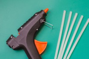
Thermoplastic injection molding is a manufacturing process in which plastic resin is heated until molten, injected into a precisely machined mold cavity, cooled until solid, and then ejected as a finished part. The defining characteristic of thermoplastics is that they can be melted and remelted without undergoing a permanent chemical change—unlike thermoset plastics, which cure irreversibly.
Thermoplastics vs. Thermosets — The Core Difference
- Thermoplastics: Soften when heated and harden when cooled. This process is reversible, allowing for recycling and reprocessing.
- Thermosets: Undergo a chemical curing reaction during molding, which permanently changes their structure. Once set, they cannot be melted again without degradation.
Basic Injection Molding Workflow for Thermoplastics
- Feeding: Plastic pellets are loaded into the hopper.
- Melting: The material is conveyed through a heated barrel by a rotating screw until it reaches the target melt temperature.
- Injection: The screw moves forward, forcing the molten plastic into the mold cavity at controlled pressure and speed.
- Cooling: Mold cooling channels remove heat, solidifying the part.
- Ejection: The mold opens, and ejector pins push the part out for the next cycle.
Key Advantages of Thermoplastic Injection Molding
- Recyclability: Scrap and rejected parts can often be reground and reused.
- High Productivity: Cycle times can be as short as a few seconds for thin-walled parts.
- Design Flexibility: Complex geometries, thin walls, and intricate details are achievable.
- Material Variety: A wide range of resins with different mechanical, thermal, and chemical properties.
Molding Process Comparison Table
| Parameter | Thermoplastic Injection Molding | Thermoset Injection Molding |
| Processing Temperature | 180–300 °C (depends on resin) | 150–250 °C (plus curing reaction) |
| Cycle Time | Seconds to minutes | Minutes (longer due to curing) |
| Recyclability | High — can be remelted | None — crosslinked structure |
| Tooling Complexity | High precision, cooling channels critical | High precision, heated mold for curing |
| Typical Applications | Automotive interiors, medical devices, packaging, and electronics housings | Electrical insulators, appliance handles, high-heat components |
| Material Examples | PP, ABS, PC, PA, POM | Phenolic, epoxy, melamine |
To explore a detailed comparison between thermoplastics and thermosets, including material properties and application examples, see our full Thermoset vs. Thermoplastic guide.
Common Thermoplastic Materials and Their Properties
Choosing the right resin is one of the most important decisions in thermoplastic injection molding. Each material comes with its own balance of strength, flexibility, temperature resistance, and chemical compatibility—and selecting the wrong one can lead to premature failure, unnecessary cost, or processing challenges.
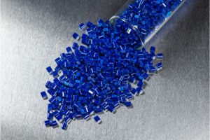
- Polypropylene (PP): Lightweight, with excellent chemical resistance and fatigue strength. Common in packaging, automotive interiors, and consumer products. It has a relatively high shrinkage rate, so mold design must compensate for dimensional accuracy.
- Acrylonitrile Butadiene Styrene (ABS): Known for high strength, impact resistance, and good surface finish. Often used in appliance housings, automotive trim, and consumer electronics. Easy to process but less resistant to harsh chemicals compared to PP or POM.
- Polycarbonate (PC): Transparent, with exceptional impact resistance and heat resistance. Common in safety equipment, lenses, and medical devices. More prone to stress cracking under certain chemicals, so material compatibility checks are important.
- Polyamide (PA, Nylon): High mechanical strength, abrasion resistance, and thermal stability. Used in gears, bearings, and under-the-hood automotive parts. Absorbs moisture, which can affect dimensional stability.
- Polyoxymethylene (POM, Acetal): Excellent dimensional stability, wear resistance, and low friction. Used in precision parts like gears, zippers, and conveyor components. Limited resistance to strong acids and bases.
Performance Comparison Table
| Material | Density (g/cm³) | Tensile Strength (MPa) | Impact Resistance | Heat Deflection Temp (°C) | Chemical Resistance | Relative Cost |
| PP | 0.90–0.91 | 25–40 | Medium–High | 95–110 | Excellent | Low |
| ABS | 1.04 | 40–50 | High | 85–100 | Fair–Good | Medium |
| PC | 1.20 | 55–75 | Very High | 125–135 | Fair | High |
| PA (Nylon) | 1.12–1.15 | 60–85 | High | 120–150 | Good | Medium–High |
| POM (Acetal) | 1.41 | 60–70 | High | 100–120 | Excellent | Medium |
Practical takeaway: For high chemical resistance with low weight, PP and POM are top choices. For maximum toughness and transparency, PC is unmatched. For a balance of surface finish and mechanical strength, ABS performs well.
Key Processing Parameters
Getting the processing parameters right is critical in thermoplastic injection molding. Each resin type has its own optimal melt & mold temperature, injection pressure, and cooling requirements. Deviating too far from these ranges can cause defects such as warpage, burn marks, short shots, or dimensional inconsistency.
Typical Parameter Ranges by Material
| Material | Melt Temp (°C) | Mold Temp (°C) | Injection Pressure (MPa) | Cooling Time (s) |
| PP | 200–250 | 20–60 | 70–120 | 10–30 |
| ABS | 210–280 | 40–80 | 80–140 | 15–40 |
| PC | 260–320 | 80–120 | 90–150 | 20–60 |
| PA (Nylon) | 240–300 | 70–100 | 80–140 | 15–40 |
| POM | 190–230 | 60–100 | 60–110 | 15–40 |
Values may vary by grade; always confirm with supplier datasheets.
How Parameter Adjustments Affect Quality
| Parameter | Too Low | Too High | Adjustment Tip |
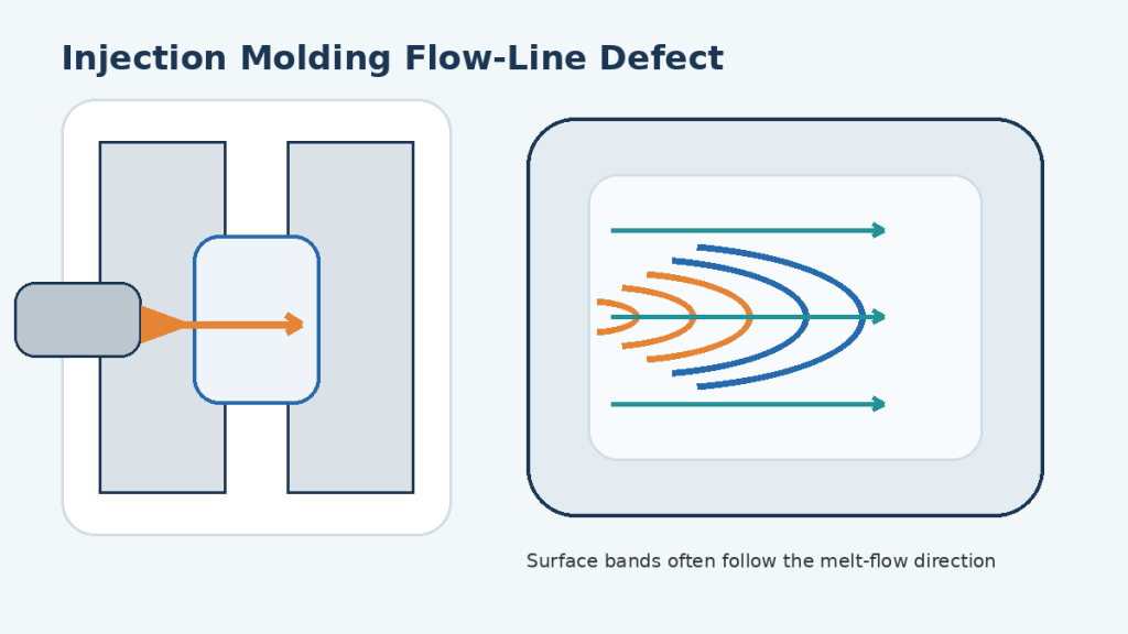
| Melt Temp | Poor flow, short shots, and weld lines | Degradation, discoloration, odor | Raise the temperature gradually until the flow improves without flashing |
| Mold Temp | Higher shrinkage variation, dull surface | Longer cycle time, possible sticking | Use higher mold temp for cosmetic parts, lower for high-output runs |
| Injection Pressure | Short shots, voids, weak weld lines | Flash, mold wear, stress marks | Balance pressure with injection speed to avoid shear burn |
| Cooling Time | Warpage, incomplete solidification | Longer cycle, reduced productivity | Optimize based on part thickness and cooling channel design |
Practical takeaway: Always run short DOE (Design of Experiments) trials when switching materials or part designs. Small tweaks in mold temp or packing pressure can dramatically improve consistency and reduce scrap.
Design Guidelines for Thermoplastic Parts
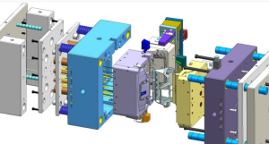
Good design practices help you get consistent quality and reduce mold rework. With thermoplastics, controlling shrinkage, wall thickness, and draft angles from the start will save significant time and cost later.
Key Design Recommendations
| Design Element | Recommendation | Why It Matters | Practical Tip |
| Wall Thickness | Uniform 2–4 mm for most thermoplastics | Reduces warpage and uneven shrinkage | Transition gradually if a thickness change is unavoidable |
| Draft Angles | ≥ 1° per side for polished surfaces; 1.5–2° for textured | Aids ejection and prevents surface damage | Increase draft for deep cores or tall ribs |
| Rib Thickness | ≤ 60% of the adjoining wall thickness | Avoids sink marks and cooling imbalances | Add fillets at rib bases for better melt flow |
| Boss Base Thickness | ≤ 80% of the adjoining wall | Prevents sinks and voids | Use gussets for strength instead of thick walls |
| Corner Radii | ≥ 0.5× wall thickness | Reduces stress concentration and improves flow | Sharp corners can cause crack initiation |
| Gate Location | Near the thickest section | Minimizes flow length and shrinkage variation | Allows packing pressure to feed shrinkage effectively |
Shrinkage Compensation
Thermoplastics shrink as they cool and solidify. The shrinkage rate depends on the resin type, filler content, and molding conditions.
General formula for cavity dimension:

Example:
- Finished part dimension: 100.00 mm
- Expected shrinkage: 1.8% (0.018)

If you’re using glass-filled PP with anisotropic shrinkage, apply different shrink factors in the flow and transverse directions based on supplier data.
Practical takeaway: A few tenths of a millimeter in mold steel can decide whether your part passes QC or requires costly rework. Always verify shrinkage with the exact resin grade during T1 sampling before committing to full production steel.
Common Molding Defects and Solutions
Even with optimized parameters and good mold design, thermoplastic injection molding can produce defects if conditions drift or material behavior isn’t fully accounted for. Recognizing the pattern of a defect and understanding its root cause lets you correct the issue without excessive trial and error.
Defect Troubleshooting Table
| Defect | Likely Causes | Recommended Solutions |
| Warpage (part deformation after ejection) | Uneven cooling, non-uniform wall thickness, excessive packing pressure | Ensure uniform wall thickness; balance cooling channels; reduce packing pressure and time; verify mold temperature consistency |
| Sink Marks (depressions on the surface) | Thick ribs/bosses, insufficient packing, early gate freeze | Reduce rib/boss thickness; relocate or enlarge gates; extend packing time until after gate freeze |
| Splay / Silver Streaks | Moisture on pellets, trapped gas/air, excessive injection speed | Keep resin sealed; pre-dry hygroscopic materials; improve venting; reduce injection speed and shear |
| Voids (internal bubbles) | Thick sections are cooling too slowly, insufficient packing, and material shrinkage | Increase packing pressure and time; redesign thick areas; improve cooling in core regions |
| Flash (excess material along parting line) | Excessive injection pressure, worn or damaged mold, insufficient clamping force | Reduce injection pressure; repair mold parting surfaces; increase clamp tonnage |
| Burn Marks (dark spots, degraded areas) | Trapped air overheating, high melt temperature, high injection speed | Improve venting; lower melt temperature; reduce injection speed |
| Short Shots (incomplete fill) | Low melt temperature, insufficient injection pressure, poor venting | Raise melt temp within safe range; increase injection pressure; improve gate/runner design |
When troubleshooting, change one parameter at a time and document results. Many defects share overlapping causes, so isolating variables is the fastest route to a stable process.
Thermoplastic Molding Applications by Industry
Thermoplastic injection molding shows up in everyday products far more often than most people realize. The car you drive, the medical device used in a hospital, the phone in your pocket, and even the cap on a water bottle—many of these parts are made using this process. Its appeal comes from being able to deliver high volumes of consistent, precisely shaped parts in materials that match the performance demands of each industry.
Automotive
In automotive design, weight reduction and durability are constant goals. Metal components deliver strength, but they add weight—a challenge when fuel efficiency and emissions regulations are tightening. We worked with a Tier 1 supplier to replace an engine bay bracket with glass-fiber reinforced polypropylene (GFPP). The result: 35% less weight, nearly 20% lower material cost, and no loss in performance during high-temperature vibration tests. In the automotive industry, this is not an isolated case—it reflects a broader trend of thermoplastics helping automakers balance regulations, cost, and performance.

Medical
In the medical device industry, every component must be consistent, traceable, and meet strict biocompatibility standards. One diagnostic equipment manufacturer struggled to find a housing material that could remain transparent and withstand ethylene oxide sterilization. We recommended a medical-grade polycarbonate (PC) that passed ISO 10993 biocompatibility testing and met optical clarity requirements. For medical clients, thermoplastic molding is not just a process—it’s a compliance and repeatability solution.

Consumer Electronics
In consumer electronics, competition is as much about the look and feel as it is about technical features. For a portable device housing, we suggested replacing painted ABS with a pre-colored PC/ABS blend. This achieved color and surface finish directly in molding, eliminating the painting step, cutting VOC emissions, and reducing cycle time by nearly 20%. For electronics brands, such changes improve both product consistency and environmental credentials.

Packaging
In fast-moving consumer goods packaging, production speed and sealing reliability are the heart of competitiveness. A food packaging plant’s bottle cap line was limited by long cycle times. By switching to a high-flow polypropylene (PP) grade and refining gate design, cycle time dropped by 12% while maintaining seal integrity. For packaging producers, that’s hundreds of extra caps per minute—directly translating to higher output and profitability.
Whether in a workshop, a lab, or an assembly line, thermoplastic injection molding’s advantage lies in adapting to each industry’s needs. From weight reduction to compliance, from surface aesthetics to production throughput, it doesn’t just shape parts—it shapes competitive advantage.

Cost Factors and Supplier Selection
Cost control in thermoplastic injection molding starts long before the first shot is molded—it begins with the right material choice, tooling approach, and supplier partnership.
Understanding the Cost Drivers
When we break down the total part cost, four elements usually dominate:
- Material: The resin itself, including any additives or colorants. Engineering-grade thermoplastics or medical-compliant resins will carry a premium.
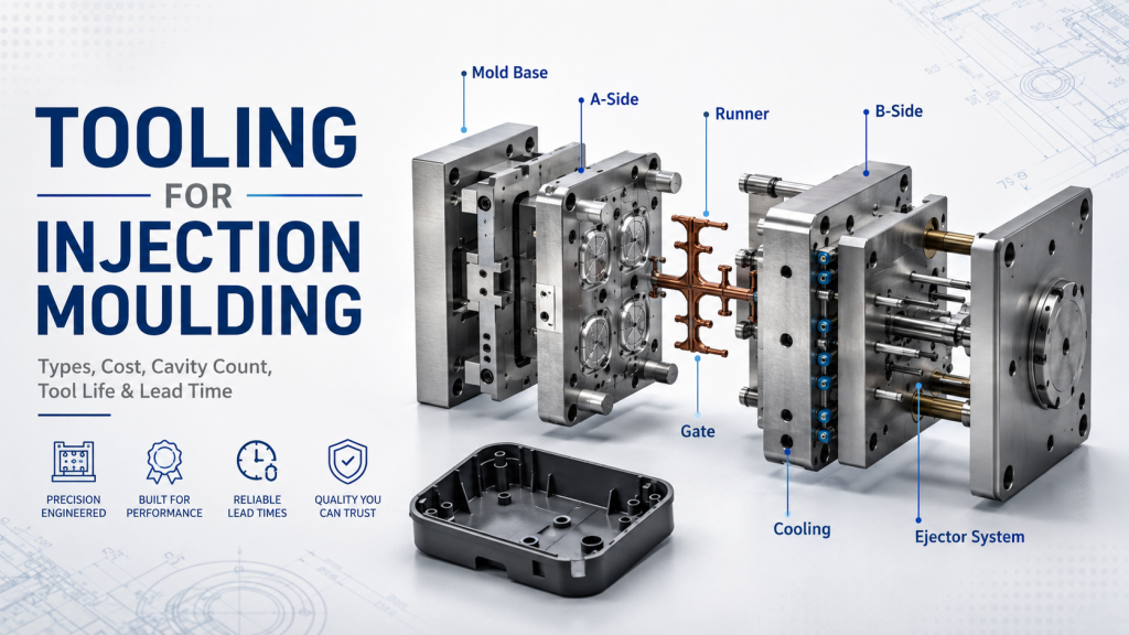
- Tooling: Mold design and build cost, influenced by complexity, number of cavities, and steel grade. High-precision multi-cavity molds cost more but reduce per-part cost at scale.
- Production Cycle: Cycle time, driven by cooling efficiency, part geometry, and process optimization. Even a two-second reduction per cycle can significantly improve annual output.
- Labor and Energy: Machine time, operator input, and energy consumption during molding and secondary operations.
Example Cost Breakdown (for a medium-volume PP part):
| Cost Component | Percentage of Total Cost |
| Material | 35–45% |
| Tooling Amortization | 15–25% |
| Labor & Energy | 20–25% |
| Overhead & QC | 10–15% |
Selecting the Right Supplier
A capable injection molder is more than just a machine shop—they are a partner in part performance, cost optimization, and on-time delivery. In our experience, the best outcomes come from suppliers who can support design-for-manufacturability (DFM) early, rather than just quoting from a print.
Supplier Evaluation Checklist:
- Technical Capability: Can they run the resin you need (including filled or specialty grades) and hold the tolerances your design demands?
- Tooling Expertise: Do they have in-house mold design and maintenance, or will they outsource?
- Quality Systems: Are they certified (ISO 9001, ISO 13485 for medical, IATF 16949 for automotive) and do they maintain robust inspection processes?
- Production Flexibility: Can they scale from prototype to full production without major delays?
- Industry Experience: Do they have proven work in your sector, with relevant case studies or references?
- Communication & Project Management – Will they provide proactive updates, or do you have to chase for information?
A low part price is meaningless if you face late deliveries, quality escapes, or mold maintenance issues. Vet suppliers not just on cost, but on their ability to help you hit design, quality, and delivery targets over the entire product lifecycle.
Sustainability and Recycling
Thermoplastics have a built-in advantage when it comes to sustainability: their molecular structure allows them to be melted, reshaped, and reused multiple times without the irreversible chemical changes that occur in thermosets. This makes them one of the few engineering materials that can close the loop in a true mechanical recycling process.
Recyclability in Injection Molding
Post-industrial scrap (sprues, runners, reject parts) can often be reground and blended back into the feedstock. Many high-volume molding operations maintain a controlled regrind ratio to reduce waste without compromising quality. Post-consumer recycled (PCR) resins are also entering more applications, especially in packaging and consumer goods—though consistent supply and quality are still challenges.
Virgin vs. Recycled Resin Performance
Recycled resin can match virgin performance in some properties, but prolonged thermal history and contamination can reduce impact strength, surface finish, or color stability. For structural or safety-critical parts, recycled content must be tested to ensure compliance with performance and regulatory requirements.
Effect of Recycled Content on PP and ABS
| Recycled Content Ratio | Tensile Strength Change | Impact Strength Change | Surface Appearance | Common Use Cases |
| 0% (Virgin) | Baseline | Baseline | Smooth, consistent | High-performance, cosmetic parts |
| Up to 20% | −2% to −5% | −5% to −10% | Minimal change | Consumer goods, light-duty components |
| 20–50% | −5% to −15% | −10% to −25% | Slight dullness, possible flow marks | Automotive trim, industrial containers |
| >50% | −15% to −30% | −25% to −40% | Noticeable dullness, color variation | Pallets, bins, non-cosmetic parts |
Values are typically ranges from production experience; actual results depend on resin grade, reprocessing method, and additives.
Design for Recycling
To maximize end-of-life recovery:
- Avoid mixed material assemblies when possible—design parts from a single polymer type.
- Use laser marking or molded-in recycling codes for easy identification.
- Consider color masterbatch selection to match available recycled resin streams.
Practical takeaway: Integrating recycled content doesn’t just check a sustainability box—it can also improve cost structure when resin prices spike. The key is to set quality limits, test early, and work with suppliers who can certify material composition.
Final Thoughts
Injection molding remains one of the most reliable and versatile methods for producing high-quality thermoplastic parts at scale. Its ability to handle complex geometries, maintain tight tolerances, and support a wide range of material properties makes it a core manufacturing process across industries.
For projects where performance, regulatory compliance, or cosmetic quality is non-negotiable, partnering with an experienced injection molding solution provider is not just a convenience—it’s a risk reduction strategy. The right partner will anticipate design challenges, fine-tune tooling, and help you reach production approval faster, while keeping part cost and quality in balance.
In short, invest in good design, respect the process, and work with expertise you can trust—your product’s success depends on it.