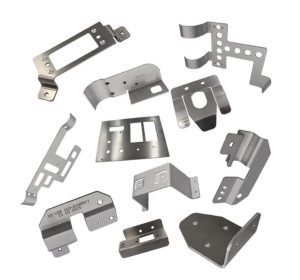
A fabrication bracket is a structural component used to connect, support, position, or reinforce other parts within an assembly. Although brackets are often simple in appearance, their geometry, material, tolerances, and manufacturing method can directly affect the strength, fit, cost, and service life of the final product.
For many industrial applications, sheet metal brackets offer an effective balance of strength, weight, manufacturability, and cost. A flat sheet can be laser cut or punched, bent into the required geometry, and finished with welding, hardware insertion, or surface treatment.
This makes bracket fabrication suitable for everything from electronics and machinery to automotive, aerospace, and construction equipment.
This guide covers the main types of fabricated brackets, material selection, manufacturing processes, DFM considerations, finishing options, and applications.
What Is a Fabrication Bracket?
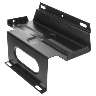
A fabricated bracket is a support or mounting component manufactured by forming metal rather than simply using a standard off-the-shelf part. Depending on the design, fabrication may include cutting, punching, bending, welding, tapping, riveting, and hardware insertion.
A typical sheet metal bracket may contain:
- Flat mounting surfaces
- One or more bends
- Bolt or screw holes
- Slots for adjustment
- Threaded holes or inserts
- Gussets or reinforcing features
- Clearance cutouts
- Welded components
The primary functions are straightforward: support a load, connect two components, maintain alignment, or create a defined mounting position.
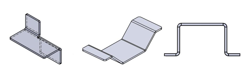
For example, an L-shaped bracket can connect two perpendicular surfaces, while a Z-shaped bracket can create an offset between two parallel mounting planes.
Why Use Sheet Metal for Brackets?
Sheet metal is particularly attractive when the part needs a relatively high strength-to-weight ratio without requiring a large amount of material removal.
Compared with machining a bracket from a solid block, sheet metal fabrication can reduce material waste and machining time. Compared with casting, it can eliminate tooling requirements for many prototypes and low-volume projects.
The result is a practical manufacturing route for custom bracket metal components, especially when geometry is primarily based on flat faces and bends.
Common Types of Sheet Metal Brackets
The best bracket geometry depends on how the component will be mounted, the direction of the applied load, and the available installation space.
L-Shaped Brackets
An L bracket uses a single 90-degree bend to create two perpendicular mounting surfaces.
Common applications include:
- Equipment mounting
- Cabinet assembly
- Structural connections
- Electronic enclosures
- Furniture and fixtures
Its simple geometry makes it one of the easiest sheet metal brackets to manufacture.
U-Shaped or Saddle Brackets
A U-shaped bracket has two bends and forms a channel-like structure.
It is useful when a component needs to be supported or enclosed from multiple sides. Typical applications include pipe supports, cable management, equipment mounts, and structural assemblies.
Z-Shaped Brackets
A Z bracket uses opposing bends to create an offset between two mounting planes.
This design is useful when two components must be connected while maintaining a specific height or horizontal offset.
For example, a Z bracket can mount a sensor or electronic component above a base plate while preserving clearance underneath.
Gusset Brackets
Gussets add triangular reinforcement to a bracket’s corner or load-bearing area.
They are particularly useful when a simple bent flange would otherwise deform under load. A gusset can significantly improve stiffness without requiring a much thicker sheet.
Offset and T-Shaped Brackets
More complex assemblies may require multiple bends or intersecting sections.
Offset brackets solve clearance and alignment problems, while T-shaped designs can connect several components around a common mounting point.
For these parts, the design must consider not only the final geometry but also whether the required bends can physically be produced with available tooling.
Choosing the Right Bracket Metal
Material selection should start with the actual service conditions rather than simply choosing the strongest available metal.
Consider:
- Required load capacity
- Weight limitations
- Corrosion exposure
- Operating temperature
- Electrical requirements
- Bendability
- Surface finish
- Production volume
- Overall cost
Common Materials for Fabricated Brackets
| Material | Key Characteristics | Typical Applications |
| Stainless Steel 304 | Corrosion resistance, strength, good formability | Industrial equipment, electronics, food equipment |
| Stainless Steel 316 | Higher corrosion resistance | Marine, chemical, medical environments |
| Aluminum 5052 | Lightweight, highly formable, corrosion resistant | Enclosures, electronics, transportation |
| Aluminum 6061 | Stronger than 5052, machinable | Structural mounts, industrial equipment |
| Cold-Rolled Steel | Strong, economical, good surface quality | Machinery, automotive, general industrial parts |
| Galvanized Steel | Steel strength with improved corrosion resistance | HVAC, construction, outdoor equipment |
| Copper | Excellent electrical and thermal conductivity | Electrical components |
| Brass | Conductive, corrosion resistant, attractive appearance | Electrical and decorative components |
For example, 5052 aluminum is often preferable when extensive bending is required, while 6061 aluminum may be selected when strength and machining performance are more important.
For highly corrosive environments, 316 stainless steel can be a better choice than standard 304.
The material should therefore be selected together with the bracket geometry and manufacturing process.
The Bracket Fabrication Process
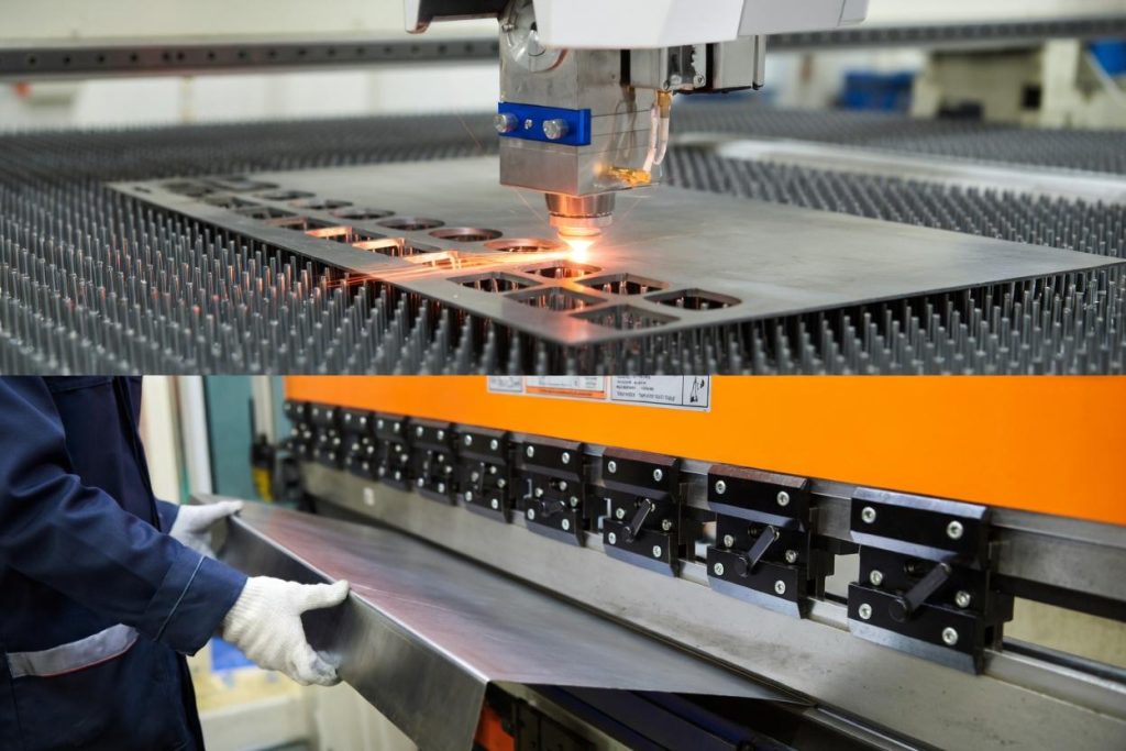
A typical bracket fabrication workflow converts a flat sheet into a finished component through several controlled operations.
Step 1: Cutting and Blanking
The process begins with a flat sheet.
Laser cutting and CNC punching are commonly used to create:
- External profiles
- Mounting holes
- Slots
- Cutouts
- Alignment features
- Bend reliefs
Laser cutting is particularly useful for prototypes and low-volume production because it can produce complex profiles without dedicated hard tooling.
CNC punching can be cost-effective for repetitive holes and simple profiles.
Step 2: Bending and Forming
The flat blank is then formed using a CNC press brake or other forming equipment.
The bending process determines the final bracket geometry and must account for:
- Material thickness
- Bend radius
- Bend angle
- K-factor
- Springback
- Tool selection
- Bend sequence
A correct flat pattern is essential. If the bend allowance is inaccurate, the finished bracket may not achieve the required dimensions.
Step 3: Secondary Operations
Depending on the design, fabricated brackets may require additional processes such as:
- Tapping
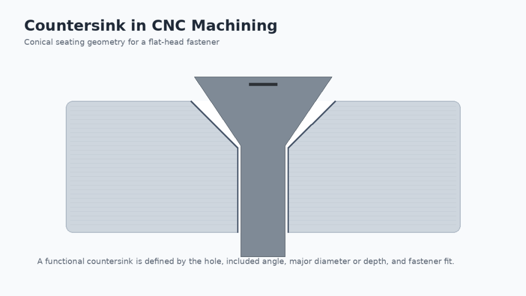
- Countersinking
- Deburring
- Reaming
- Riveting
- PEM hardware insertion
- Welding
- Assembly
For example, a bracket may receive PEM nuts after bending so that it can accept screws without requiring access to the opposite side.
Step 4: Welding and Assembly
Welding becomes useful when the bracket consists of multiple components or requires permanent reinforcement.
TIG and MIG welding are common options, with the choice depending on material, thickness, geometry, appearance, and production requirements.
For high-volume or repeatable assemblies, minimizing unnecessary welded components can simplify production and improve consistency.
Step 5: Surface Finishing
The final operation may include powder coating, anodizing, plating, passivation, or bead blasting.
Finishing is not only cosmetic. The correct treatment can improve corrosion resistance, wear resistance, electrical properties, or surface durability.
DFM Considerations for Sheet Metal Brackets
Good bracket design begins before manufacturing. Design for manufacturability (DFM) helps prevent bending problems, distorted holes, unnecessary operations, and avoidable production costs.
Choose a Practical Bend Radius
The minimum inside bend radius depends on the material, thickness, grain direction, tooling, and forming process.
An excessively tight radius can cause cracking, particularly in less formable materials.
Instead of specifying an arbitrary small radius, use a radius appropriate for the selected material and thickness.
Keep Holes Away From Bend Lines
A hole positioned too close to a bend can deform during forming.
As a general design principle, leave sufficient distance between holes and bend lines so that the hole remains outside the primary deformation zone.
The exact minimum distance should be determined according to material thickness, bend radius, tooling, and the manufacturer’s process capability.
Add Bend Relief Where Necessary
When a bend terminates near an edge or another feature, a bend relief may be required.
Without adequate relief, the material can tear, buckle, or deform during bending.
This is particularly important for U-shaped, Z-shaped, and other multi-bend brackets.
Consider Tooling Clearance
A bracket may look manufacturable in CAD but still be impossible to bend if the tooling cannot access the required surfaces.
Short flanges, deep channels, narrow gaps, and closely spaced bends can all create press-brake interference.
For complex geometries, review the bend sequence and tooling before finalizing the design.
Avoid Unnecessary Tight Tolerances
Not every dimension on a bracket needs a tight tolerance.
Applying unnecessarily strict tolerances increases inspection requirements and can increase manufacturing cost without improving the product’s actual performance.
Instead, identify critical dimensions such as:
- Mounting-hole position
- Overall assembly height
- Interface dimensions
- Alignment features
- Critical bend angles
Then assign tighter tolerances only where function requires them.
Design Around the Fasteners
The bracket and its fasteners should be designed as one system.
Check:
- Hole diameter
- Thread specification
- Head clearance
- Washer clearance
- Edge distance
- Tool access
- PEM insert requirements
- Assembly sequence
This is especially important when brackets are installed inside confined assemblies.
Surface Finishing for Fabricated Brackets
The appropriate finish depends on both the material and the operating environment.
Powder Coating
Powder coating provides a durable protective layer and is widely used for steel and aluminum brackets.
It can improve:
- Corrosion resistance
- Scratch resistance
- Appearance
- Color consistency
It is a practical choice for machinery, equipment frames, enclosures, and consumer-facing components.
Anodizing
Anodizing is commonly used for aluminum.
It improves surface hardness and corrosion resistance while providing a controlled appearance. It is often selected for electronic housings, equipment components, and lightweight structural brackets.
Electroplating
Zinc, nickel, and other plating processes can improve corrosion resistance and surface properties.
Plating is useful when the bracket requires a specific appearance or additional protection without adding a thick coating.
Passivation
Passivation is commonly applied to stainless steel to improve corrosion resistance by removing free iron and promoting a more stable passive surface.
Bead Blasting
Bead blasting produces a uniform matte texture and can be used to improve appearance and prepare surfaces for subsequent finishing.
Applications of Sheet Metal Brackets
Because brackets are fundamentally connection and support components, their applications span almost every manufacturing sector.
Automotive
Automotive applications include:
- Battery mounting brackets
- Sensor mounts
- Engine compartment supports
- Wiring and cable brackets
- Chassis components
- Interior mounting hardware
Weight, vibration, corrosion, and dimensional stability are often key considerations.
Electronics and Telecommunications
Sheet metal brackets are widely used inside:
- Server racks
- Control cabinets
- Network equipment
- PCB assemblies
- Power supplies
- Display systems
These parts often prioritize accurate hole positioning, compact geometry, grounding requirements, and easy assembly.
Aerospace
Aerospace brackets can be used for equipment mounting, interior structures, cable management, and instrumentation.
Weight reduction is particularly important, while material selection, traceability, dimensional control, and process consistency become increasingly important for demanding applications.
Industrial Equipment
Industrial machinery uses brackets for:
- Motor mounting
- Sensor positioning
- Guarding
- Structural support
- Pipe and cable management
- Equipment assembly
For these applications, load capacity and durability usually take priority over cosmetic appearance.
Construction and HVAC
Brackets can support pipes, ducts, conduits, panels, and other building-system components.
Galvanized steel and stainless steel are frequently considered when the bracket will face moisture or outdoor exposure.
Custom Fabricated Brackets vs. Standard Brackets
Standard brackets are convenient when the required dimensions and load characteristics already match an existing product.
Custom fabricated brackets become more valuable when the application requires:
- Non-standard dimensions
- Specific mounting-hole patterns
- Special offsets
- Custom bend angles
- Integrated fasteners
- Weight reduction
- Special materials
- Specific surface finishes
- Prototype or low-volume quantities
A custom bracket can also consolidate multiple components into one part.
For example, instead of using a flat plate, spacer, and separate angle bracket, a single formed sheet metal component may perform all three functions.
This can reduce assembly steps, fastener count, and potential points of failure.
When Should You Choose Sheet Metal Bracket Fabrication?
Sheet metal fabrication is usually a strong choice when the bracket:
- Has mostly planar surfaces
- Requires one or more bends
- Needs relatively fast prototyping
- Will be produced in low or medium volumes
- Benefits from lightweight construction
- Does not justify dedicated molding or casting tooling
For highly complex 3D geometries, very tight dimensional tolerances, or heavily machined interfaces, CNC machining or another manufacturing process may be more appropriate.
In many real projects, the best solution is a combination of processes—for example, sheet metal fabrication for the main bracket plus CNC machining for critical interfaces.
Custom Sheet Metal Bracket Fabrication with Kemal
When a bracket needs to move from CAD to a functional prototype or production batch, manufacturing capability should be evaluated alongside design support.
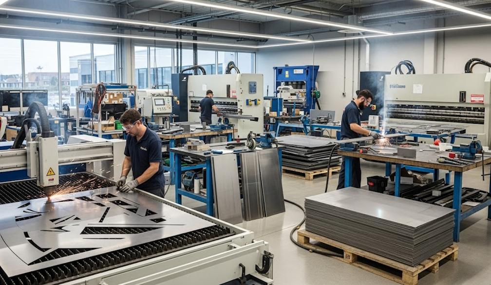
Kemal’s Sheet Metal Fabrication Services supports custom sheet metal parts from prototypes to low-volume production, including laser cutting, punching, bending/forming, welding, PEM hardware insertion, tapping, riveting, and sub-assembly. The service covers materials such as 304/316 stainless steel, 5052/6061 aluminum, cold-rolled steel, and galvanized steel, with finishing options including powder coating, anodizing, electroplating, and bead blasting.
For bracket projects, this integrated process is useful because the same project can cover the flat pattern, forming, hardware, finishing, and assembly requirements instead of treating each operation separately.
Kemal also provides DFM review for sheet metal designs, including checks related to bend radius, hole-to-bend distance, and relief features.
Need a Custom Fabrication Bracket?
If you already have a CAD model or 2D drawing, you can upload the bracket design, specify the material, quantity, critical tolerances, and surface finish requirements, and request a quote with DFM feedback.
Upload Your Bracket Design and Request a Quote
This approach is particularly useful when you are still validating the design, because potential manufacturability issues can be identified before production rather than after the first parts are made. Kemal states that uploaded files are treated as confidential and that NDA support is available.
Conclusion
A well-designed fabrication bracket is more than a bent piece of metal. Its performance depends on the interaction between geometry, material, tolerances, forming method, fasteners, and surface treatment.
For most custom sheet metal bracket projects, the key steps are:
- Define the load, mounting, and environmental requirements.
- Select a suitable bracket metal based on strength, weight, corrosion resistance, and formability.
- Design the flat pattern around realistic bend radii and tooling constraints.
- Keep holes, reliefs, and fasteners compatible with the forming process.
- Use laser cutting or punching for the blank, followed by controlled bending and secondary operations.
- Select surface finishing according to the service environment.
- Validate critical dimensions and interfaces before moving into larger production volumes.
When the geometry is suitable, sheet metal bracket fabrication provides a flexible and economical path from prototype to production. For custom designs, early DFM review and clear communication of drawings, quantities, materials, tolerances, and finishing requirements can make the transition from CAD to finished component much more predictable.