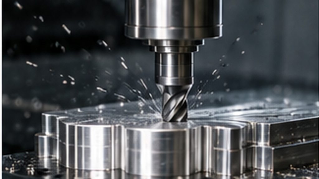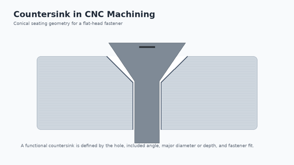
Computer-aided design (CAD) defines product geometry and design intent before manufacturing begins. In a production workflow, CAD is used to build 2D drawings and 3D models, communicate critical requirements, support design-for-manufacturability (DFM) checks, develop mold structures, and release controlled files to suppliers. CAM converts approved geometry into manufacturing instructions, while CAE evaluates product or process behavior through simulation.
For buyers and engineers, the key issue is not which CAD software is used but whether the released data is complete, manufacturable, and revision-controlled. A reliable supplier handoff usually includes a controlled 3D model, a 2D drawing for critical requirements, material and finish specifications, quantity, revision, and acceptance criteria. This guide explains how CAD moves from product modeling through DFM, mold design, drawing communication, and final file delivery.
What Is Computer-Aided Design (CAD) and What Does It Do?
Computer-aided design is the digital definition of a product or component. In manufacturing, CAD gives design, engineering, tooling, sourcing, and quality teams a common reference before physical production begins.
Depending on the system and workflow, it can support:
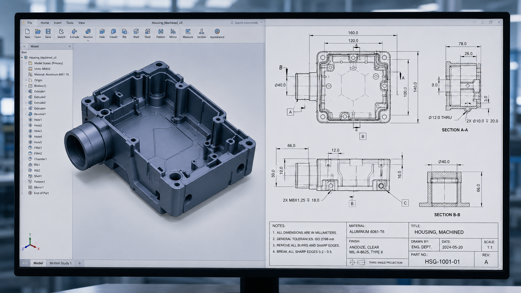
- 2D drafting and manufacturing drawings
- 3D solid and surface modeling
- Parametric dimensions and design relationships
- Assemblies and interference checks
- Sheet-metal and weldment definitions
- Mold, fixture, and tooling design
- Mass-property and clearance review
- Drawing generation and annotation
- Design variants and configurations
- Data exchange with CAM, CAE, metrology, and PLM systems
The value is not simply faster drawing. A controlled CAD model creates a common reference for design, manufacturing, sourcing, tooling, and quality. For an injection-molded product, the workflow is connected: CAD defines the part; DFM tests the geometry against manufacturing constraints; mold design converts the approved part into a tooling structure; drawings capture requirements that geometry alone cannot; and revision control determines which data package the supplier is authorized to manufacture. This value is lost when files have unclear revisions, broken geometry, missing units, conflicting drawings, or requirements stored only in email.
CAD, CAM, and CAE: Different Jobs in One Workflow
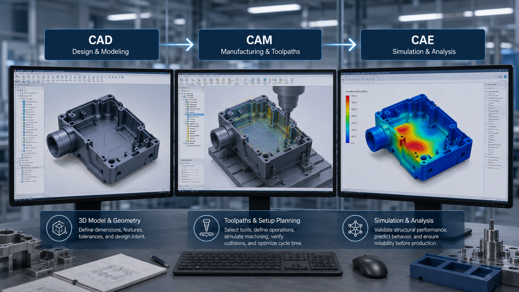
| System | Main purpose | Typical output | Manufacturing question answered |
|---|---|---|---|
| CAD | Define product geometry and design intent | 3D model, assembly, 2D drawing, bill of materials | What must be made? |
| CAM | Plan machine operations from approved geometry | Toolpaths, setup data, machine code, operation plan | How will the geometry be machined? |
| CAE | Analyze performance or process behavior | Stress, thermal, flow, motion, or other simulation results | How may the design behave under defined conditions? |
| CMM/metrology software | Plan and evaluate measurement | Inspection program, point data, comparison report | Does the produced part meet acceptance requirements? |
| PLM/PDM | Control product data and revisions | Approved records, workflow, access, change history | Which data is current and authorized? |
CAD is the starting definition, not an automatic guarantee of manufacturability. CAM cannot correct an inaccessible internal corner, and simulation cannot replace an approved material specification or measurement plan.
Main Types of CAD Models
2D CAD
Two-dimensional CAD creates views, sections, dimensions, symbols, and annotations. It remains important for manufacturing because a drawing can communicate tolerances, datums, finishes, notes, threads, inspection points, and other requirements that may not be embedded in a 3D model.
2D drawings are also common for flat profiles, sheet cutting, simple layouts, and legacy parts. Their main limitation is that complex geometry can be harder to interpret without a 3D reference.
3D solid modeling
Solid models define a closed volume. They are widely used for mechanical parts, assemblies, mass properties, interference checks, mold design, CNC machining, and many additive processes.
A valid solid is usually easier to offset, section, measure, and manufacture than an open collection of surfaces. Still, imported solids can lose feature history, design intent, and parametric relationships.
Surface modeling
Surface modeling is useful for complex exterior shapes, styling surfaces, aerodynamic forms, parting surfaces, and Class-A appearance work. A manufacturing workflow may combine surface tools with solid modeling.
Surface quality matters. Gaps, overlaps, poor continuity, self-intersections, or unclear trim boundaries can create problems during tooling, CAM, meshing, or inspection.
Parametric modeling
Parametric models use dimensions, constraints, features, and relationships to control geometry. They can make families of parts and controlled changes efficient when the model is built with stable references.
Poorly structured dependencies can make a small revision break downstream features. A robust model uses clear datums, deliberate feature order, meaningful names, and limited fragile references.
Direct modeling
Direct modeling changes geometry without relying on a feature history. It can be effective for imported parts, rapid concepts, fixture design, and local modifications. It may be less suitable when the project depends on a carefully controlled parametric product family.
The choice is not ideological. Use the modeling method that preserves design intent, supports expected changes, and transfers reliably to manufacturing.
What a 3D CAD Model Does Not Automatically Communicate
A supplier can measure nominal geometry from a 3D model, but several critical requirements may remain unknown.
| Missing information | Why it matters | Where to define it |
|---|---|---|
| Material grade and condition | Changes shrinkage, machining, finish, strength, and cost | Drawing, specification, or controlled RFQ |
| Dimensional tolerances | Determines process, setup, inspection, and acceptance | 2D drawing or approved model-based definition |
| GD&T and datum scheme | Controls functional relationships and measurement setup | Drawing or validated MBD workflow |
| Surface finish and texture | Affects manufacturing operations and appearance | Drawing, finish standard, texture specification, sample |
| Threads and inserts | Geometry alone may not identify class, standard, or installation | Drawing notes and hardware specification |
| Heat treatment and coating | Changes dimensions, hardness, wear, corrosion, and sequence | Drawing and process specification |
| Cosmetic zones | Defines where marks, gates, parting lines, or defects matter | Marked drawing, appearance standard, approved sample |
| Inspection method | Different measurement methods can produce different results | Quality plan and drawing |
| Revision and authority | Prevents manufacturing the wrong design | Title block, PDM/PLM, purchase order, transmittal |
When the 3D model and drawing conflict, the purchase agreement should state which source governs. Do not leave precedence to assumption.
CAD File Formats for Manufacturing
No single file format is best for every task. Native files preserve more design intelligence but require compatible software. Neutral formats improve exchange but may lose history or annotations. Mesh files represent a tessellated surface rather than exact design geometry.
| Format | Data type | Good use | Main caution |
|---|---|---|---|
| STEP (.step/.stp) | Neutral exact 3D geometry | General supplier exchange for machining, tooling, molding, and assemblies | Feature history and some metadata may not transfer |
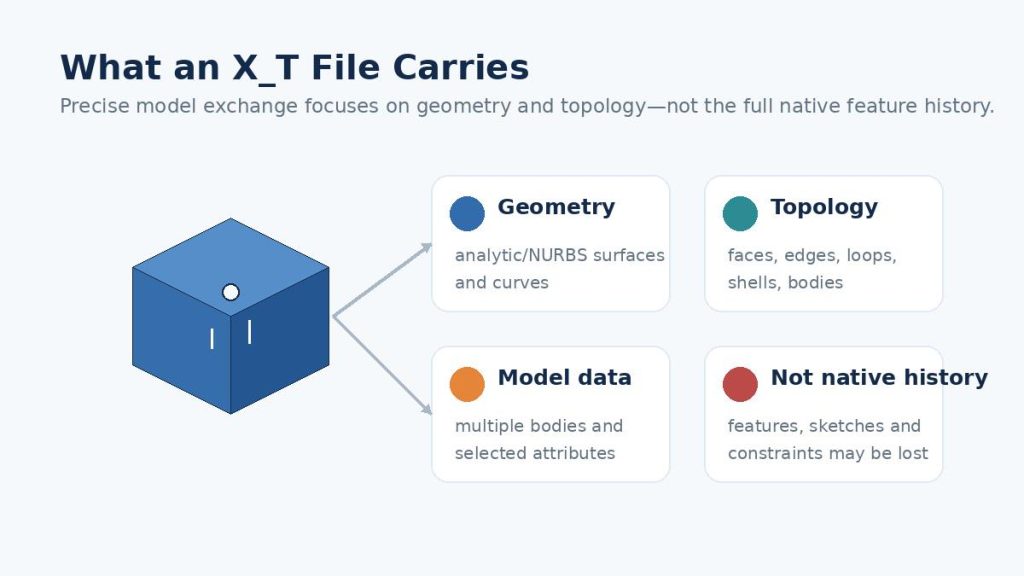
| Parasolid (.x_t/.x_b) | Neutral geometry kernel format | High-quality solid exchange between compatible systems | Confirm software compatibility and units |
| IGES (.igs/.iges) | Older neutral curves/surfaces/solids | Legacy surface exchange | Can produce disconnected surfaces or require repair |
| Native CAD | Original feature-based model | Design collaboration and controlled changes | Version and software compatibility must match |
| STL | Triangulated mesh | Many 3D-printing workflows and visualization | Not ideal as the only source for precision machining or tooling |
| 3MF | Mesh plus additional print-related data | Supported additive workflows | Supplier and machine workflow must support it |
| DXF/DWG | 2D/3D drafting data | Profiles, laser/waterjet cutting, drawings, layouts | Layers, scale, units, splines, and duplicate entities need control |
| Viewable document | Released drawing, notes, approvals, visual reference | Not a substitute for editable exact geometry |
Practical exchange rule
For custom manufacturing, a strong default package is an exact 3D neutral model such as STEP, a controlled PDF drawing, and the native file when collaboration requires feature history. Send STL only when a mesh is appropriate and the resolution is controlled.
Before release, open the exported file in a second viewer or system. Check units, body count, surface closure, assembly position, missing components, thread representation, and critical dimensions.
Building Manufacturing-Ready CAD: From Product Model to DFM Release
Manufacturing-ready design means the geometry and requirements fit the intended process and can be inspected. The same part may need different design rules for CNC machining, injection molding, or 3D printing.
Step 1: Define function and CTQs
Identify what the part must do and which characteristics are critical to quality. Examples include sealing, bearing alignment, optical appearance, electrical isolation, snap engagement, press fit, fluid flow, and assembly clearance.
Do not assign tight tolerances to every feature. Link each critical requirement to a functional reason and a measurement method.
Step 2: Choose the likely manufacturing process
Part geometry should reflect the process. CNC machining needs tool access, practical internal radii, workholding, and setup planning. Injection molding needs draft, stable wall thickness, gate and ejection strategy, shrinkage allowance, and tooling access. Additive manufacturing needs orientation, support, feature-size, and post-processing decisions.
See 3D printing vs. CNC machining when comparing prototype routes. If the project may move into tooling, use rapid prototyping to validate function without treating prototype behavior as automatic proof of production-tool behavior.
Step 3: Establish a datum and assembly strategy
Choose stable functional references. Model mating parts and define how the product locates, fastens, seals, and tolerates variation. A dimension chain should reflect assembly function rather than convenient CAD edges.
Step 4: Run DFM before release
DFM should happen before the design is frozen for tooling. For injection-molded parts, the review should check draft, wall-thickness transitions, ribs and bosses, undercuts, parting direction, gate and ejection constraints, shrinkage assumptions, cosmetic zones, and tolerance risks. A useful DFM review produces decisions: what can remain as designed, what should change, and which issues must be resolved during mold design.
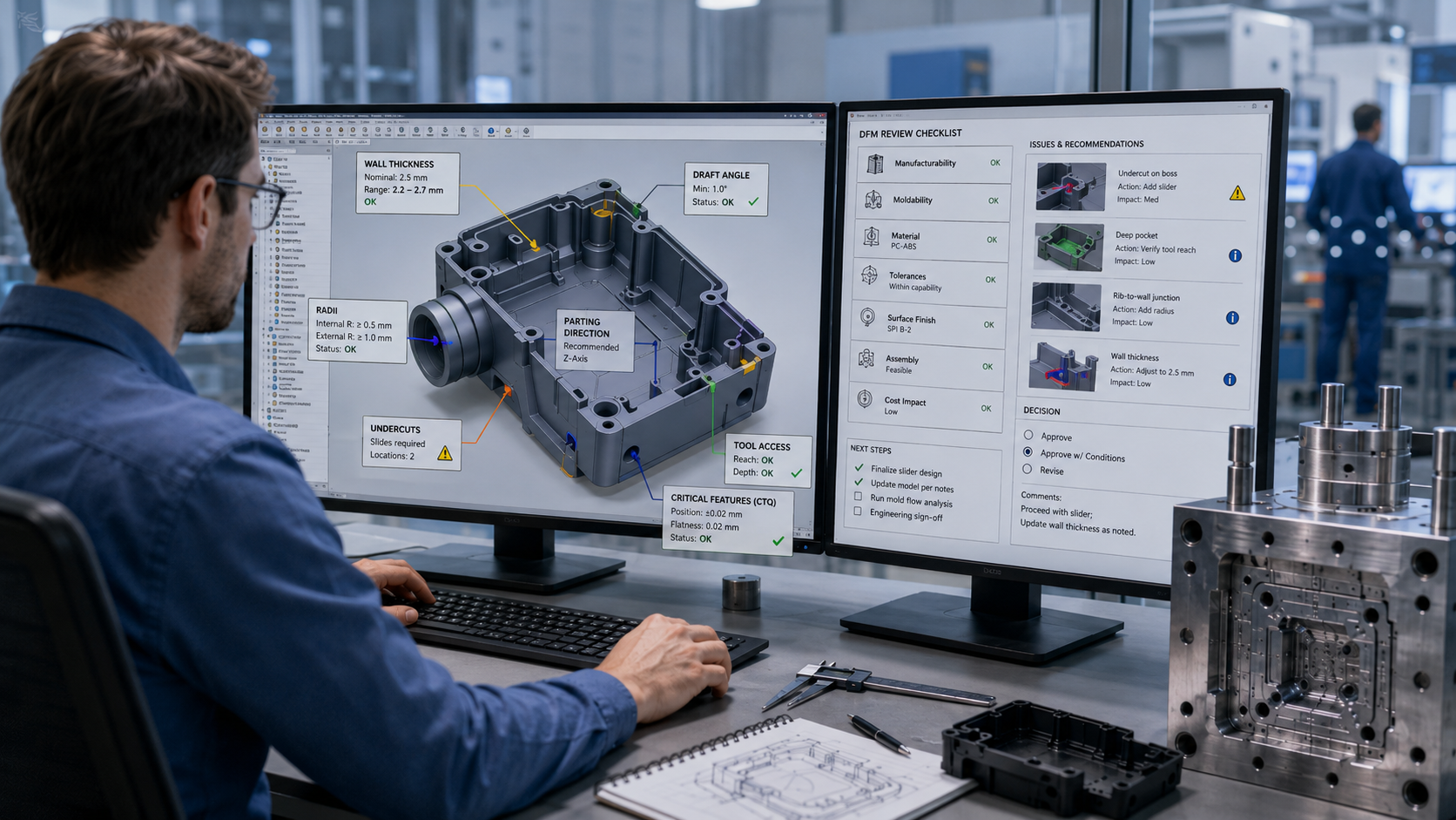
If the product is moving toward tooling, review Kemal’s Mold Design and DFM capabilities before the mold structure is finalized.
Step 5: Release controlled data
Freeze the revision, export the agreed formats, verify the exports, issue a transmittal, and record approvals. Include open deviations or approved exceptions with the package.
CAD for CNC Machining
A machinable model must allow cutting tools to reach the required surfaces while the workpiece can be held securely and inspected.
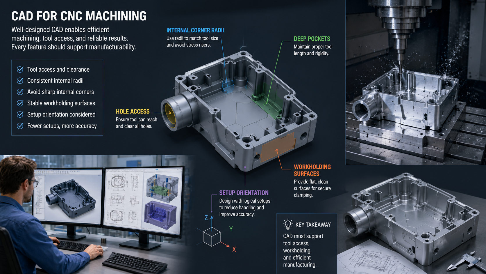
Key CAD considerations include:
- Internal corner radii compatible with tool diameter and reach
- Deep pockets and slender tools
- Tool access for holes, undercuts, and side features
- Workholding surfaces and setup count
- Thin walls and distortion risk
- Thread depth, class, and callout
- Deburring and edge-break requirements
- Stock condition and material direction
- Tolerance concentration and datum transfer between setups
- Surface finish by functional area
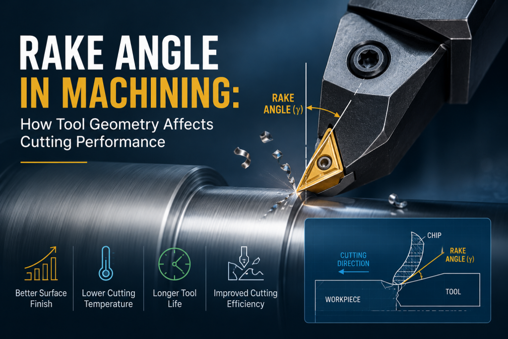
The CAM programmer can create toolpaths only after these physical constraints are understood. A visually simple part can still be expensive if it requires multiple orientations, long tools, custom fixtures, or inspection after each setup.
Kemal’s CNC machining services and guide to CNC machining prototypes explain the connected production path.
How CAD Supports Injection Mold Design
Injection-molded CAD must serve two linked definitions: the plastic part the customer needs and the mold structure required to produce it repeatedly. Product CAD should therefore be reviewed not only for nominal shape, but also for how the geometry affects parting, gating, ejection, cooling, side actions, shrinkage, appearance, and tolerance control. Important decisions include:
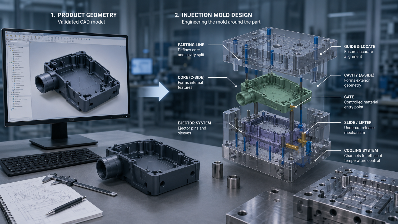
- Resin and shrinkage assumptions
- Wall-thickness transitions
- Draft direction and texture allowance
- Parting line and shutoffs
- Gate location and vestige
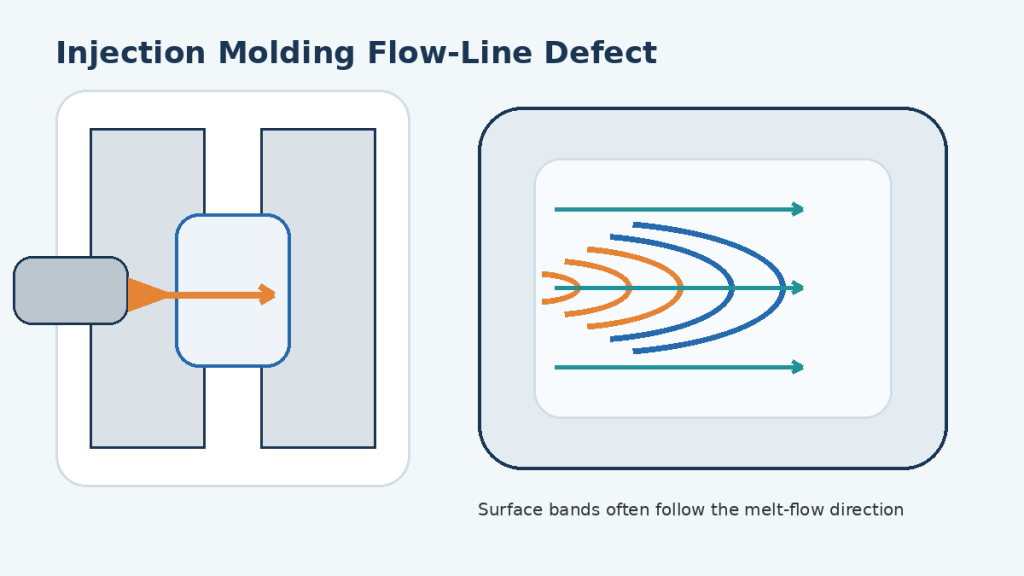
- Weld lines, air traps, and flow behavior
- Ribs, bosses, gussets, and thick intersections
- Undercuts, slides, lifters, or design alternatives
- Ejection marks and part release
- Cooling access and likely hot spots
- Cosmetic zones and approved defect standard
- Assembly and tolerance stack-up
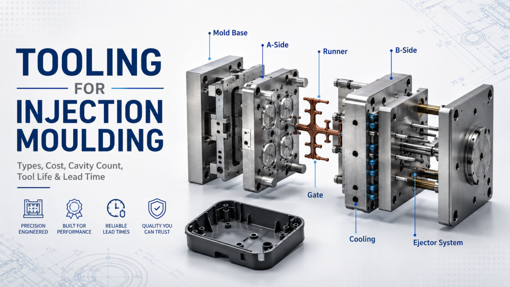
A nominal product model is only the starting point for mold design. After DFM review, the tooling team translates the part into the core and cavity split, parting surfaces and shutoffs, runners and gates, cooling channels, vents, ejection, slides or lifters, steel-safe conditions, and mold interfaces. These tooling decisions can feed back into the product model when draft, wall transitions, undercuts, gate vestige, ejection marks, or tolerance strategy require a design change.
Before steel release, the approved part revision, DFM actions, and mold structure should be aligned. See Kemal’s Mold Design service for the design-to-tooling path and DFM support.
CAD for 3D Printing
Additive manufacturing converts geometry into layers, but the result still depends on process, orientation, material, support, resolution, thermal behavior, and post-processing.
Check:
- Minimum wall and feature size for the selected process
- Orientation-sensitive strength and appearance
- Support contact and removal access
- Enclosed volumes and powder/resin drainage
- Hollow sections and escape holes
- Machining allowance on critical surfaces
- Thread and insert strategy
- Warpage or curl risk
- Mesh resolution and file repair
- Build volume and part segmentation
An STL can appear smooth on screen while containing coarse facets, holes, inverted normals, or incorrect units. Validate the exported mesh and retain the exact CAD model as the controlled master when possible.
CAD Drawings, Tolerances, and GD&T: Communicating Design Intent
The 3D model defines nominal geometry. The drawing or approved model-based definition communicates how much variation is acceptable, which features are functionally critical, and how conformance should be evaluated. This is why supplier communication should use the model and drawing as a controlled pair rather than treating a 3D file as the entire manufacturing specification.
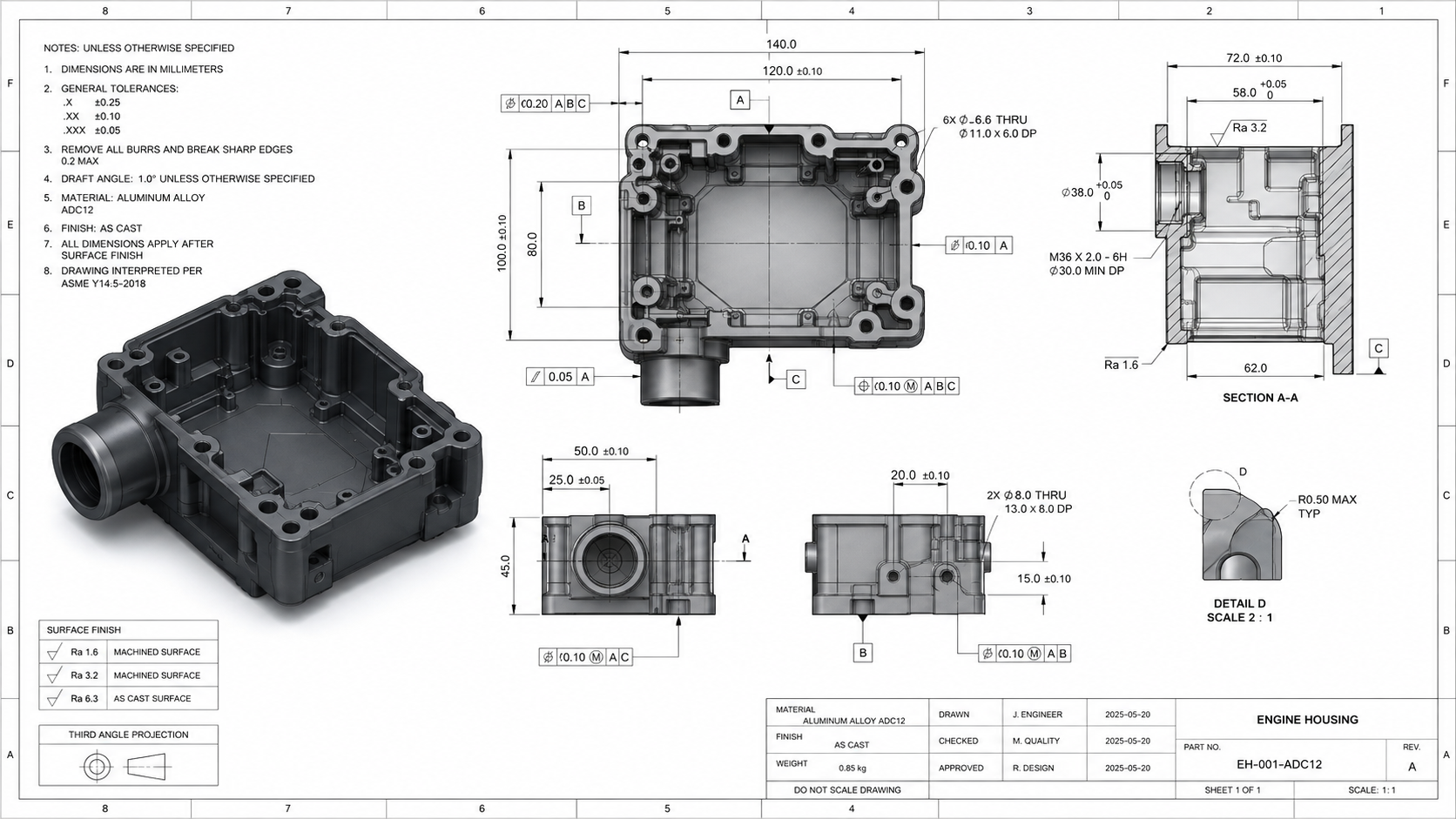
Use a release process that defines:
- Unique part number and revision
- Approved native, neutral, drawing, and specification files
- Revision history and reason for change
- File precedence when sources conflict
- Approval owner and date
- Supplier acknowledgement
- Impact review for tooling, fixtures, gauges, stock, work in progress, and finished inventory
- Effective date or serial/lot break
- Disposition of old data and old parts
Do not use names such as final.step, final2.step, or latest_revised.step as revision control. The purchase order and transmittal should identify the authorized revision explicitly. At supplier handoff, send one clearly identified release package so the 3D model, 2D drawing, specifications, revision, and RFQ or purchase references all point to the same approved design state.
Common CAD-to-Manufacturing Problems
| Problem | Production impact | Corrective action |
|---|---|---|
| Missing or incorrect units | Part scaled incorrectly | State units in model, drawing, RFQ, and export verification |
| Open, overlapping, or corrupt geometry | CAM, tooling, or meshing errors | Repair and validate the exact master before release |
| STL used as the only precision source | Faceted or approximate geometry | Provide STEP/Parasolid/native CAD plus drawing when exact geometry is required |
| Drawing and model conflict | Supplier guesses which requirement governs | Define precedence, correct both files, and re-release the revision |
| Over-toleranced drawing | Higher cost, longer inspection, reduced process options | Tie tolerances to function and measurement capability |
| Missing draft or tooling access | Mold complexity, sticking, or redesign | Complete DFM before tool design release |
| Unmachinable corner or feature | Long tools, EDM, extra setups, or redesign | Add practical radii or change feature architecture |
| Unclear cosmetic requirements | Disagreement over visible defects | Mark appearance zones and use an approved standard/sample |
| Uncontrolled revision | Wrong parts, rework, obsolete stock | Use part/revision control and supplier acknowledgement |
| No inspection definition | Different interpretations of conformance | Agree datums, method, sampling, reports, and acceptance rules |
The first response should be to clarify the controlled data, not to ask manufacturing to “make it look like the screenshot.”
CAD and DFM Review Before Mold Design or Quotation
Use this pre-RFQ checklist:
Geometry
- The model opens without repair errors.
- Units, body count, assembly position, and part orientation are correct.
- Threads, inserts, draft, radii, and thin features are intentional.
- Suppressed, hidden, construction, and reference geometry are understood.
- Exported neutral files match the controlled native model.
Requirements
- Material and condition are specified.
- Critical dimensions and datums reflect function.
- Surface finish, appearance, color, coating, and heat treatment are defined.
- Quantity, prototype/production intent, and target process are stated.
- Inspection and documentation needs are clear.
Data control
- Part number and revision match across all files.
- The governing source and file precedence are stated.
- Open questions and deviations are documented.
- The supplier has acknowledged receipt of the correct revision.
Request a CAD and DFM Review
Already have a part model? Send the controlled 3D CAD file together with the 2D drawing, material or resin, expected quantity or annual volume, critical dimensions, finish or cosmetic requirements, target process, revision, and target delivery date. Kemal can review the data for manufacturability and identify issues that should be resolved before mold design or quotation. View Kemal’s Mold Design and DFM capabilities and submit your CAD data package for review.
How a Supplier Should Review CAD
A useful supplier review should return clear decisions rather than a generic “file received” message.
| Review area | Useful supplier feedback |
|---|---|
| Process fit | Recommended process, alternatives, and rejected options with reasons |
| Manufacturability | Tool access, draft, walls, undercuts, distortion, ejection, support, or fixture risks |
| Tolerances | Features that require clarification, special control, or alternative datums |
| Material | Availability, condition, process behavior, and approved substitutions |
| Inspection | Measurement method, datum setup, gauges, reports, and sampling |
| Cost | Geometry and requirements driving setup, cycle, tooling, scrap, inspection, or secondary work |
| Schedule | Approval gates, material/tool dependencies, sample timing, and open inputs |
| Revision | Confirmed file list, part number, revision, and unresolved conflicts |
A supplier who asks precise questions is often reducing project risk. Fast quotation without confirming inputs may only hide assumptions until production.
CAD Data for Quality Inspection
Inspection should trace back to controlled design intent. The quality team may use the model for CMM programming, profile comparison, fixture design, scan alignment, first-article reporting, or visual overlays. The drawing provides datums, tolerances, notes, and acceptance criteria.
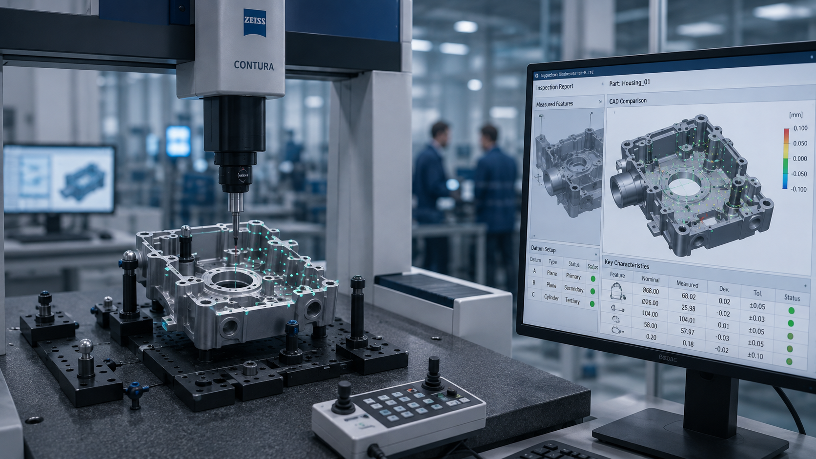
Before measurement, agree on:
- Drawing revision and model revision
- Datum simulation and part restraint
- Part-conditioning time and environment
- Measurement method and equipment
- Point strategy, fitting method, and reporting rules
- Surface or edge definition
- Sampling plan
- Treatment of measurement uncertainty
- Disposition process for nonconformance
Kemal’s quality assurance page provides broader inspection context. Project-specific acceptance criteria must still come from the approved data package.
Frequently Asked Questions
What is computer-aided design?
Computer-aided design is the use of software to create, modify, analyze, and document products or components. In manufacturing, CAD supplies the controlled geometry and design intent used for drawings, tooling, machining, prototyping, assembly, and inspection.
What is the difference between CAD and CAM?
CAD defines what the product should be. CAM plans how a machine will manufacture the approved geometry through operations, tools, setups, and toolpaths. CAM depends on CAD but does not replace design requirements.
Is a 3D CAD model enough for manufacturing?
Not always. A model may not communicate material, tolerances, GD&T, surface finish, threads, heat treatment, cosmetic zones, inspection, or revision authority. A controlled 2D drawing and RFQ specifications are often needed.
What is the best CAD file format for manufacturers?
There is no universal best format. STEP or Parasolid are common for exact neutral 3D exchange, native CAD supports design collaboration, PDF communicates released drawings, DXF/DWG supports many 2D workflows, and STL/3MF supports selected additive workflows. Confirm the supplier’s system and purpose.
Can a manufacturer quote from an STL file?
It may be possible for some additive or approximate work, but STL is a triangulated mesh and may not preserve exact design geometry. Precision machining, tooling, or controlled production usually benefits from exact CAD plus a drawing.
Why do the CAD model and drawing need the same revision?
Conflicting revisions create uncertainty over geometry and acceptance. Matching controlled revisions help the supplier manufacture, inspect, and document the intended design without guessing.
How does DFM change a CAD model?
DFM may change radii, draft, wall transitions, ribs or bosses, undercuts, parting direction, gate and ejection strategy, datum approach, tolerances, support requirements, or feature architecture. For molded parts, these changes should be resolved before mold structure is finalized, and each approved change should be tied to the correct CAD and drawing revision.
What should I send for a manufacturing quote?
Send the controlled 3D model, 2D drawing, material or resin and finish, quantity or annual volume, critical features, target process, inspection requirements, revision, and delivery objective. Include mating parts or assembly information when they affect function. If the project is intended for injection molding, include cosmetic requirements and any known tooling or mold-life expectations that affect the review.
Final Takeaway: CAD Is the Starting Point for DFM and Mold Design
Computer-aided design gives manufacturing teams a precise digital starting point, but reliable production requires more than nominal geometry. A complete handoff combines exact CAD, controlled drawings, process-aware DFM, functional tolerances, revision control, inspection planning, and clear commercial inputs.
Already have a 3D part model? Review Kemal’s Mold Design and DFM capabilities, then submit your CAD model and project requirements for a manufacturability review before tooling release.