Quick answer: SFM stands for Surface Feet per Minute. In machining, it describes the linear speed of the cutting edge relative to the workpiece surface. SFM is a cutting-speed value, while RPM is the spindle’s rotational speed. The two are connected by tool or workpiece diameter.
If you have read a tooling catalog, programmed a CNC mill, set spindle speed on a lathe, or compared cutting recommendations, you have probably seen SFM listed beside feed and speed data. The term is simple, but applying it correctly matters because the same RPM can create very different cutting speeds when diameter changes.
This guide explains what SFM means, how to calculate it, how to convert SFM to RPM, why material and tooling change the appropriate value, and how to use SFM as a practical starting point rather than a fixed number.
What Is SFM in Machining?
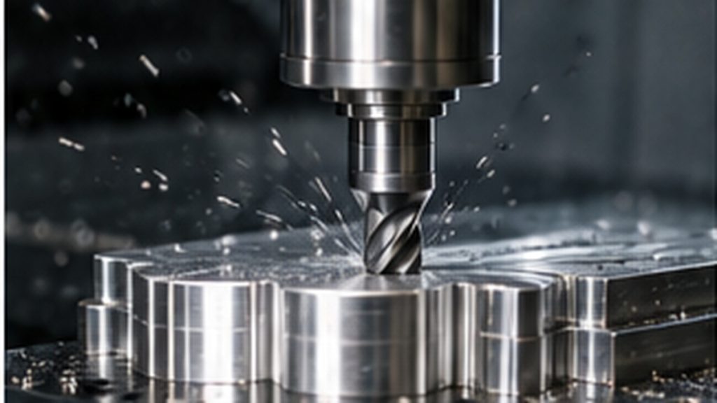
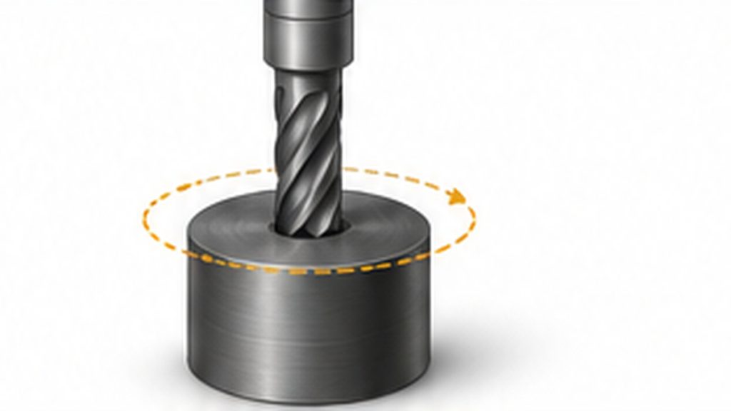
SFM, or Surface Feet per Minute, is the distance that the cutting surface travels in one minute, expressed in feet per minute. In a rotating cutting process, the outside edge of a tool or workpiece travels around a circular path. SFM converts that circular motion into a linear surface-speed value.
That distinction is useful because cutting conditions are governed by the speed at the cutting interface, not by RPM alone. A small-diameter tool must rotate faster than a large-diameter tool to produce the same surface speed.
| A simple way to think about SFM
RPM tells you how many revolutions occur each minute. SFM tells you how fast the cutting edge is moving across the material at the cutting diameter. |
Why SFM Matters in CNC Machining
Cutting speed influences the thermal and mechanical conditions at the tool-workpiece interface. If the chosen speed is poorly matched to the material, tool, and operation, the result may be excessive heat, rapid wear, built-up edge, poor chip control, unstable cutting, or an unnecessarily slow cycle.
SFM is therefore one part of a larger parameter system. It should be considered together with feed per tooth or feed per revolution, depth of cut, radial engagement, tool geometry, coolant strategy, machine rigidity, and the required surface finish.
| Parameter | What It Describes | Typical Unit |
| SFM / cutting speed | Linear speed at the cutting diameter | ft/min |
| RPM | Spindle revolutions per minute | rev/min |
| Feed rate | How fast the tool advances through the cut | in/min or mm/min |
SFM vs. RPM vs. Feed Rate
These values are related, but they are not interchangeable. SFM describes cutting speed. RPM is the rotation required to achieve that speed at a given diameter. Feed rate controls how quickly the cutting edge progresses through the workpiece.
The key point: when tool diameter changes, you normally recalculate RPM if you want to maintain the same SFM. When RPM changes, feed rate may also need to change if you want to maintain the same chip load.
For example, two end mills running at the same RPM do not have the same SFM if their diameters are different. Likewise, increasing RPM without adjusting feed can reduce chip load and potentially cause rubbing in some milling conditions.
SFM Formula: How to Calculate Surface Feet per Minute
For inch-based calculations, SFM can be calculated from cutting diameter and spindle speed:
| SFM = (π × Diameter in inches × RPM) ÷ 12
SFM ≈ (0.2618 × Diameter × RPM) |
The factor of 12 converts inches per minute into feet per minute. Use the diameter at the actual cutting point. For a standard end mill cutting near its full diameter, that may be the nominal tool diameter. For some profile or ball-nose milling operations, the effective cutting diameter can be smaller, so using the nominal diameter may overstate the true cutting speed.
Metric Equivalent: Cutting Speed in Meters per Minute
In metric machining data, cutting speed is usually written as Vc in meters per minute rather than SFM. The relationship is:
| Vc (m/min) = (π × Diameter in mm × RPM) ÷ 1000 |
The underlying concept is the same: linear surface speed at the cutting diameter.
How to Convert SFM to RPM
When a tool manufacturer recommends a cutting speed in SFM, you can convert that value into spindle speed for your tool diameter:
| RPM = (SFM × 12) ÷ (π × Diameter in inches)
RPM ≈ (SFM × 3.82) ÷ Diameter in inches |
Example: 0.500-Inch End Mill at 400 SFM
Suppose you want to run a 0.500-inch diameter end mill at an illustrative cutting speed of 400 SFM:
| RPM = (400 × 3.82) ÷ 0.500
RPM ≈ 3,056 |
This example shows the conversion method only. It is not a universal recommendation for a particular material or tool. Actual starting values should come from the cutting-tool manufacturer’s data and then be adjusted for the application.
Metric Example
For a 10 mm tool at an illustrative cutting speed of 100 m/min:
| RPM = (1000 × 100) ÷ (π × 10)
RPM ≈ 3,183 |
How Tool Diameter Changes RPM
For a fixed SFM, RPM changes inversely with diameter. A smaller tool needs more revolutions per minute to cover the same linear surface distance. A larger tool needs fewer.
| Tool Diameter | Relative RPM at Same SFM | Practical Effect |
| Smaller | Higher | May approach spindle-speed limits |
| Medium | Moderate | Often within a broad machine operating range |
| Larger | Lower | Torque and tool engagement may become more important |
| Changing diameter | Recalculate | Do not carry RPM over blindly |
This relationship also matters in turning. As the workpiece diameter changes, the RPM required to maintain the same surface speed changes. CNC lathes can use constant surface speed modes to manage this automatically within programmed spindle limits.
What Determines the Right SFM?
There is no single correct SFM for every material. Published cutting-speed ranges are starting points tied to specific tooling systems and assumptions. The correct value for a real job depends on several interacting factors.
1. Workpiece Material and Condition
Different materials generate different cutting forces, heat, chip behavior, and tool wear. Even within the same material family, alloy, hardness, heat treatment, casting condition, and work-hardening behavior can change the appropriate cutting speed.
2. Cutting-Tool Material
High-speed steel, carbide, ceramic, CBN, PCD, and other tool materials have different thermal and wear capabilities. A cutting speed that is reasonable for one tool material may be unsuitable for another.
3. Tool Coating and Geometry
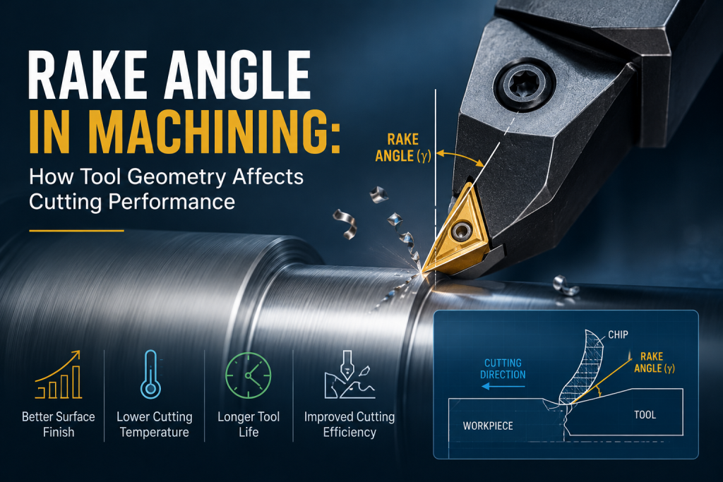
Coatings can change heat resistance, friction, and wear behavior. Rake angle, edge preparation, flute count, helix, chipbreaker geometry, and edge sharpness also affect how a tool handles a given surface speed.
4. Operation and Engagement
A finishing pass, full-width slot, high-efficiency milling path, drilling cycle, and heavy roughing cut do not load the tool in the same way. Radial engagement, axial depth, interrupted cutting, and entry/exit conditions all matter.
5. Machine and Setup Rigidity
Machine condition, spindle power, toolholder quality, tool overhang, workholding, part stiffness, runout, and vibration can limit usable cutting parameters even if a catalog value appears higher.
6. Coolant, Lubrication, and Heat Management
Flood coolant, minimum-quantity lubrication, air blast, or dry cutting can change thermal behavior and chip evacuation. The appropriate strategy depends on the material, tool, and operation.
Recommended image filename: sfm-material-tool-selection.jpg
If you are comparing machinability across metals and plastics, the Kemal materials guide provides a useful starting point for reviewing common CNC material families before process planning.
How to Choose a Starting SFM
The safest way to select a starting cutting speed is to work from application-specific tool data rather than a generic internet chart. A practical sequence is:
- Identify the exact workpiece material, grade, and hardness or condition when relevant.
- Identify the exact cutting tool, substrate, coating, diameter, and geometry.
- Match the operation: milling, turning, drilling, slotting, profiling, roughing, finishing, or another process.
- Use the tool manufacturer’s recommended cutting-speed range for that material and operation.
- Convert the selected SFM or m/min value to RPM using the actual cutting diameter.
- Check the machine’s maximum spindle speed, available power or torque, toolholding limits, and workholding rigidity.
- Set feed using the manufacturer’s chip-load or feed-per-revolution guidance, then calculate feed rate from RPM.
- Run a controlled first cut and inspect sound, chips, spindle load, surface finish, tool wear, and dimensional stability before optimizing.

| Do not treat a catalog value as a guarantee
Manufacturer recommendations are starting conditions. Real parts introduce variables such as tool overhang, thin walls, interrupted cuts, deep cavities, poor chip evacuation, machine limits, and finish requirements. |
How to Adjust SFM During Machining
When the first setup does not behave as expected, avoid changing SFM in isolation. Use the machining symptoms to decide whether cutting speed, feed, engagement, rigidity, coolant, or tool selection is the real issue.
| Observed Symptom | Possible Parameter Issue | What to Check |
| Rapid flank wear or excessive heat | Cutting speed may be too aggressive | Verify tool data, coolant strategy, engagement, and tool wear pattern |
| Built-up edge or material welding | Speed, tool geometry, lubrication, or chip evacuation may be unsuitable | Check material-specific tooling and edge condition |
| Chatter | May be a stability problem rather than an SFM problem | Check overhang, workholding, radial engagement, spindle speed zones, and tool condition |
| Poor finish | Could involve speed, feed, runout, vibration, or edge wear | Inspect the full setup before changing only RPM |
| Rubbing or very light chips | Chip load may be too low for the RPM | Check feed per tooth or feed per revolution |
When surface appearance is a key drawing requirement, cutting parameters are only part of the outcome. Toolpath, tool condition, workholding, polishing, blasting, anodizing, plating, and other secondary operations may also matter. For post-machining options, see surface finishing options.
SFM in Milling, Turning, and Drilling
Milling
In milling, the cutting diameter is usually based on the rotating cutter. For standard end milling, the nominal diameter often works as the calculation diameter. In ball-nose or profile milling, however, the effective diameter at the actual contact point may be smaller than the nominal tool diameter.
Turning
In turning, surface speed is based on workpiece diameter at the cutting point. Because diameter changes during facing and contouring, the RPM needed for constant surface speed also changes. Machine controls can compensate with constant surface speed, subject to a programmed maximum RPM.
Drilling
For drilling, cutting speed is generally related to drill diameter. As drill diameter decreases, the RPM required to maintain a given SFM increases. Small drills can therefore encounter spindle-speed limitations before reaching the recommended cutting speed.
Common SFM Mistakes
Using RPM as if it were cutting speed: RPM has no meaning as a cutting-speed value without diameter.
Copying one RPM to a different tool diameter: Changing diameter changes surface speed, so the RPM must be recalculated.
Using a generic material chart as the final setting: Tool substrate, coating, geometry, engagement, and machine conditions can shift the usable range.
Ignoring effective cutting diameter: Profile and ball-nose milling may cut at a smaller effective diameter than the tool’s nominal size.
Changing speed but forgetting feed: If RPM changes and feed stays fixed, chip load changes.
Chasing chatter only with RPM: Chatter can involve rigidity, overhang, workholding, toolpath, engagement, and dynamic stability.
Exceeding machine or toolholding limits: Calculated RPM must still be safe for the spindle, holder, tool, and workpiece setup.
FAQ: SFM in Machining
What does SFM stand for?
SFM stands for Surface Feet per Minute. It is an imperial cutting-speed unit that describes linear surface speed at the cutting diameter.
Is SFM the same as RPM?
No. SFM is surface speed; RPM is rotational speed. RPM depends on both the target SFM and the cutting diameter.
How do I calculate RPM from SFM?
For inch units, use RPM = (SFM × 12) ÷ (π × diameter in inches). A common approximation is RPM = (SFM × 3.82) ÷ diameter.
Does a smaller tool need more RPM?
Yes, if the target SFM remains the same. A smaller diameter must rotate faster to achieve the same linear surface speed.
Is higher SFM always better?
No. Higher cutting speed can improve productivity in the right application, but excessive speed can shorten tool life or create heat-related problems. The usable range depends on the material, tool, operation, and setup.
Where should I get the correct SFM for a tool?
Start with the cutting-tool manufacturer’s data for the exact tool, workpiece material, and operation. Then adjust based on machine capability and actual cutting results.
How does SFM affect feed rate?
SFM determines RPM through diameter. If you want to maintain the same chip load after changing RPM, the programmed feed rate normally changes as well.
From Cutting Speed to a Manufacturable CNC Part
Understanding SFM helps you set up a machining process, but a production-ready part requires more than one cutting-speed calculation. Material condition, geometry, tolerances, surface requirements, tool access, workholding, inspection, and quantity all influence the final process plan.
For broader process and capability information, see Kemal’s CNC machining services. If you have a specific component, submit the material grade, 2D drawing or 3D CAD model, quantity, critical tolerances, and required surface condition for a project-specific manufacturability and process review.
Key takeawaySFM is the linear cutting speed at the tool-workpiece interface. Use it to translate tool-maker cutting-speed guidance into RPM for the actual cutting diameter, then coordinate RPM with feed, engagement, tooling, and machine conditions. Treat published values as starting points and validate them on the real setup. |