Quick answer: An .x_t file is the text-based Parasolid XT format used to exchange precise 3D CAD geometry. It is especially useful when the sending and receiving applications use the Parasolid modeling kernel. For manufacturing handoff, treat the X_T model as the geometry source and pair it with a controlled 2D drawing or requirement sheet for tolerances, material, finish, revision, and other production-critical information.
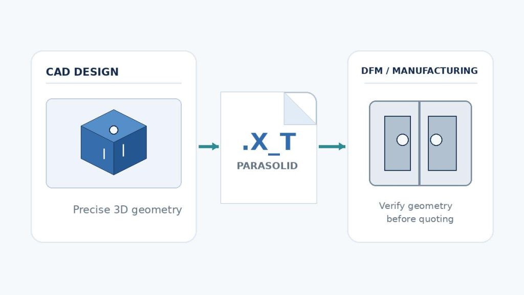
An X_T file often appears when an engineer, designer, mold maker, or machine shop exchanges a 3D model outside the original CAD system. The file can carry accurate solid and surface geometry without forcing the recipient to own the native authoring software. That makes it useful for design review, DFM, mold development, CAM preparation, supplier quoting, and cross-CAD collaboration.
The main difficulty is not understanding the extension itself. It is knowing what information the file preserves, whether the receiver can read its Parasolid version, and what additional data must travel with the model so manufacturing intent is not lost. This guide focuses on those practical questions.
What Is an X_T File?
An X_T file is a text-encoded Parasolid XT model file. Parasolid is a geometric modeling kernel developed by Siemens and used by many CAD, CAM, CAE, and manufacturing applications. Siemens describes Parasolid XT as a data format for precise model exchange across Parasolid-based applications, and its free JT2Go viewer can display and measure Parasolid XT geometry.
The “T” in X_T distinguishes the text representation from the binary X_B representation. Both are intended to carry Parasolid model data; the difference is mainly how that data is encoded and stored. A text X_T file can be opened in a text editor, but the content is structured model data rather than a human-readable engineering drawing.
What data does an X_T file contain?
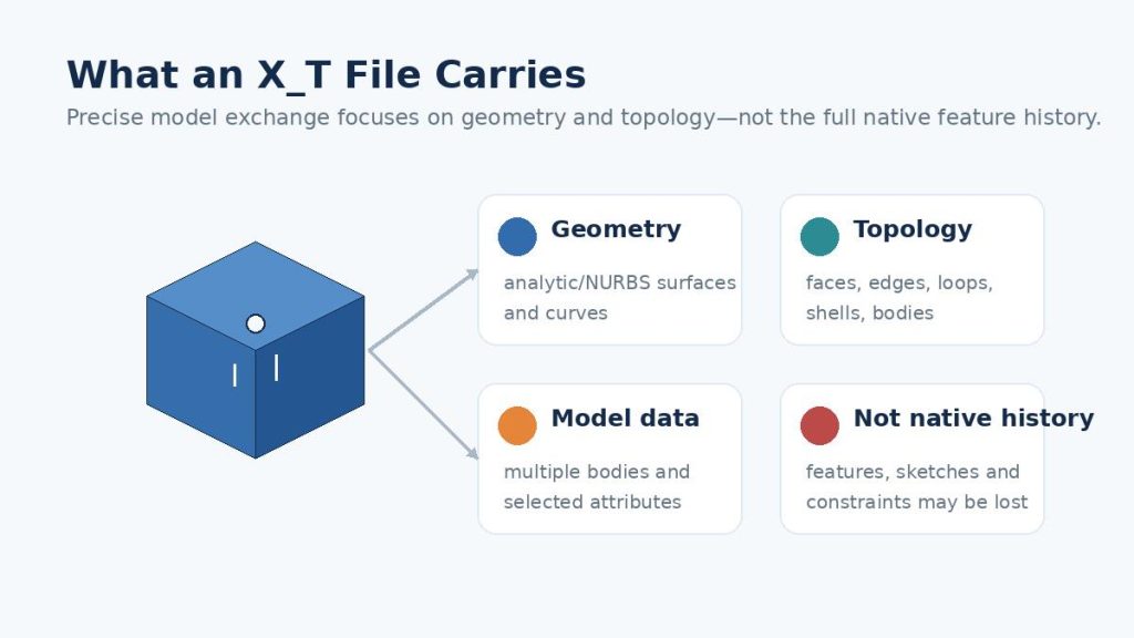
For manufacturing, the most important point is that X_T is primarily a geometry-and-topology exchange format. A properly exported file can represent precise B-rep solids and surfaces, including the relationships that define faces, edges, loops, shells, and bodies.
| Data type | What to expect in an X_T transfer | Manufacturing implication |
| Precise geometry | Solid and surface geometry, curves, faces, edges, and body topology. | Suitable for dimensional model review, DFM, tooling work, and CAM when the import is valid. |
| Multiple bodies | A model can contain more than one body, depending on the source application and export settings. | Confirm that every intended body is present after import. |
| Colors / selected attributes | Some applications preserve colors, names, and selected model attributes through Parasolid import/export. | Useful for organization, but do not rely on color alone to communicate tolerances or process requirements. |
| Native feature history | Usually not transferred as the original parametric feature tree, sketches, design intent, and editable constraints. | The receiver often gets imported geometry or a base feature rather than the authoring history. |
| 2D drawing requirements | Not a substitute for a released drawing containing GD&T, critical dimensions, notes, finish, inspection requirements, or revision control. | Send a 2D drawing or requirement sheet when those items affect the quote or manufacturing plan. |
This distinction matters because a model can look geometrically correct while still being incomplete as a manufacturing definition. A supplier may be able to create toolpaths or start a mold review from the 3D body, yet still need the 2D drawing to know which dimensions are critical, which surfaces are cosmetic, what finish is required, and which revision is approved.
X_T vs. X_B: What Is the Difference?
X_T and X_B are both Parasolid XT exchange formats. X_T stores the model in text form, while X_B stores it in binary form. In day-to-day CAD exchange, the geometric intent can be equivalent; the more practical differences are file representation, size, inspectability, and the software workflow around them.
| Format | Encoding | Typical reason to use it | Practical note |
| X_T | Text / ASCII-style representation | Common exchange format; easier to identify and inspect as a text file. | Usually larger than an equivalent binary representation, but widely recognized in engineering workflows. |
| X_B | Binary representation | Compact storage and transfer in workflows that accept Parasolid binary files. | Not human-readable in a text editor; confirm the recipient accepts X_B before sending. |
If a customer or supplier explicitly requests one form, use that form. If no preference is stated, X_T is a practical default when Parasolid is accepted, because the extension is widely recognized and easy to identify in a mixed CAD package.
How to Open an X_T File
The best way to open an X_T file is with CAD software that supports Parasolid import, or with a viewer designed for Parasolid XT. Siemens offers JT2Go as a free viewer for JT and Parasolid XT data. Commercial CAD systems and translation tools may also import X_T, but supported Parasolid versions can vary by product release and license.
Method 1: Open it in your CAD application
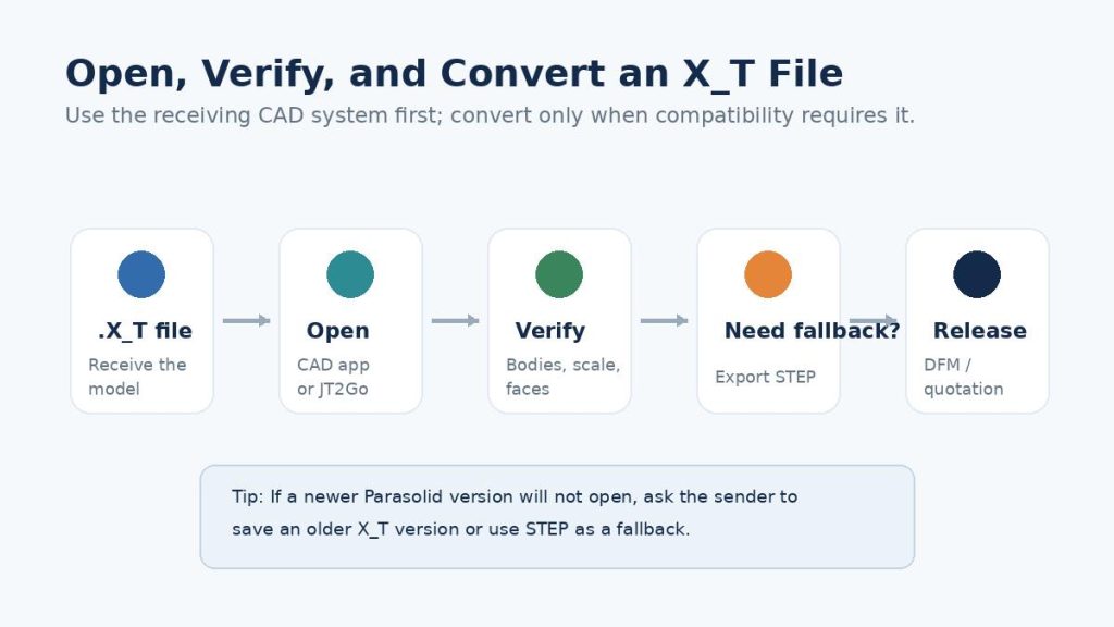
Use the application’s Open, Import, or Insert command and choose Parasolid / X_T. After import, do not immediately assume the translation is production-ready. Perform a short receiving inspection:
- Confirm the expected number of solid and surface bodies.
- Check units and overall part size against a known dimension.
- Rotate, section, and inspect small fillets, holes, thin walls, and complex transitions for missing or damaged faces.
- Check whether component names, colors, or body organization matter to the next process.
- Compare the imported model with the released drawing or a source screenshot when the project is critical.
Method 2: Use a Parasolid viewer
A viewer is useful when you only need to inspect, rotate, measure, or communicate about the model. Siemens JT2Go is an official no-cost option for viewing Parasolid XT. Other CAD viewers and translators also support X_T, but their import capabilities and supported versions differ.
Method 3: Convert it to a format your software supports
If the receiving application cannot read the file, convert the X_T model to a neutral CAD format such as STEP. Prefer conversion in a trusted CAD or translation environment where you can verify the result. For confidential or unreleased product data, avoid uploading the model to an unknown online converter without checking its security, retention, and intellectual-property terms.
How to Convert an X_T File to STEP, IGES, or STL
Conversion is straightforward in principle: open the X_T file in software that reads Parasolid, verify the imported geometry, then export to the target format. The important decision is choosing a target format that matches the next task.
Convert X_T to STEP for general CAD and manufacturing exchange
STEP is usually the first fallback when the recipient does not support X_T. It is a neutral ISO-based product-data exchange family and is broadly supported across CAD and manufacturing systems. Use STEP when the priority is portable solid/surface geometry across different CAD kernels or supplier environments.
Convert X_T to IGES only for workflows that still require it
IGES remains available in many CAD systems, but it is commonly used for legacy exchange or specific surface workflows. For a modern solid-model manufacturing handoff, STEP or Parasolid is generally easier to manage because they are more naturally aligned with solid B-rep exchange.
Convert X_T to STL only when a mesh is the intended output
STL represents a tessellated mesh rather than the exact analytic or NURBS B-rep geometry used in an X_T solid. That can be appropriate for 3D printing, visualization, or mesh-based processing, but it is not a like-for-like replacement for precise CAD geometry. Once you convert to STL, downstream editing and measurement depend on the mesh resolution rather than the original exact surfaces.
| Conversion rule: Convert only when the next application requires it. Every additional translation is another opportunity for geometry, attributes, units, naming, or assembly organization to change. When both sides can work directly with Parasolid XT, keeping the X_T file can reduce unnecessary translation steps. |
X_T vs. STEP vs. IGES vs. STL
There is no single “best CAD format” for every situation. The right choice depends on the receiving software, whether exact B-rep geometry is required, whether model-based definition or PMI must travel with the file, and whether the next step is editing, manufacturing, inspection, visualization, or additive production.
| Format | Geometry type | Best fit | Main caution |
| X_T | Precise Parasolid B-rep | Exchange between Parasolid-capable CAD/CAM/CAE systems; DFM; mold and machining workflows. | Receiving software must support the file’s Parasolid version and intended model content. |
| STEP | Precise neutral B-rep/product data | Broad cross-CAD supplier exchange and long-lived neutral handoff. | Import behavior and PMI support depend on STEP application protocol and receiver implementation. |
| IGES | Legacy neutral geometry exchange | Legacy systems and some surface-centric workflows. | Solid/topology healing can be more cumbersome than with modern B-rep exchange formats. |
| STL | Triangle mesh | 3D printing, visualization, mesh processing. | Not exact CAD geometry; no native parametric features and limited manufacturing definition. |
When is X_T better than STEP?
X_T is especially attractive when the sender and receiver both work in Parasolid-based or Parasolid-compatible environments. Siemens positions XT as translation-free interoperability between Parasolid-based applications. In practical terms, that can reduce kernel-to-kernel conversion of the core geometry. The benefit does not mean every application-level feature, constraint, annotation, or assembly relationship will behave like a native file; it means the geometric model is being exchanged in the underlying Parasolid representation.
When is STEP the safer choice?
STEP is often safer when you do not know the recipient’s modeling kernel, when multiple suppliers use different CAD systems, or when a neutral standardized exchange package is required. In many manufacturing RFQs, it is useful to keep both options available: send X_T when the supplier prefers Parasolid, or STEP when a neutral cross-system format is more reliable for the specific software chain.
Common X_T File Problems and How to Fix Them
1. “Unsupported file version” or the file will not open
Parasolid evolves over time, while each CAD release ships with a particular Parasolid reader or translator. A receiving application can therefore reject a model saved in a newer Parasolid version than it supports. Autodesk, for example, has documented cases where Fusion users had to save a newer X_T file back to an older Parasolid version or use STEP as a fallback.
- Ask the sender to export an older Parasolid version that the receiving CAD system supports.
- Update the receiving software or translator when appropriate.
- Use STEP as a neutral fallback if backward-saving is not available.
- Record the exported file version in the RFQ package when cross-company compatibility is a recurring issue.
2. The model opens, but bodies or faces are missing
This can result from export settings, unsupported model content, damaged source geometry, or translation behavior. Compare body count and key dimensions. If the issue is localized, ask for a re-export from the source model rather than repairing the supplier copy without traceability. If the source application supports export options for solids, surfaces, or selected bodies, confirm that the intended geometry was included.
3. The model is the wrong size
Unit handling is usually managed automatically by modern CAD translators, but a receiving check is still worthwhile. Verify one known overall dimension before DFM, CAM, or quotation. A scale error can invalidate tooling clearances, stock calculations, cycle assumptions, and inspection planning.
4. You can see the geometry, but cannot edit the original features
That is normal for a neutral or kernel exchange file. The recipient generally receives imported geometry rather than the original native feature tree. Direct-edit tools can modify faces and bodies, and some CAD systems can recognize features after import, but those are reconstruction workflows—not restoration of the original parametric history.
5. Manufacturing intent is missing even though the model is valid
This is one of the most important supplier-handoff problems. A geometrically complete X_T model may still omit or fail to communicate critical tolerances, GD&T, surface finish, thread specifications, cosmetic surfaces, molding texture, heat treatment, inserts, inspection notes, and controlled revision information. The fix is procedural: send a complete RFQ package, not only a 3D file.
How to Share an X_T File With a Manufacturer Without Losing Design Intent
A good CAD handoff separates two questions: “What is the shape?” and “What must the manufactured part satisfy?” The X_T model primarily answers the first question. Your drawing, RFQ notes, and specification package answer the second.
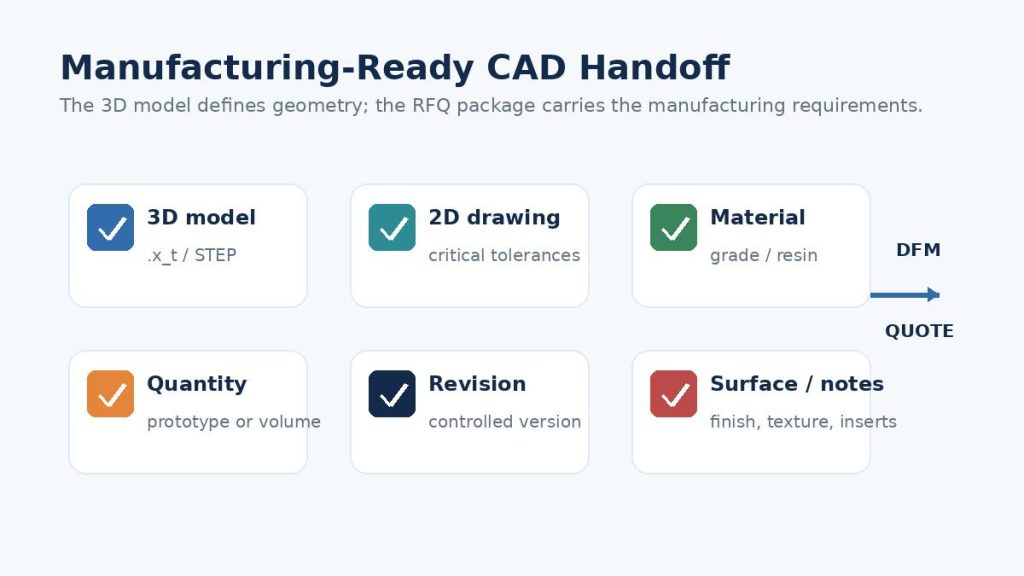
Use this manufacturing handoff checklist
- Controlled 3D model: Send the released .x_t file and make the revision identifiable in the filename or accompanying document.
- 2D drawing: Include critical dimensions, datum scheme, GD&T, threads, tolerances, inspection notes, and any dimensions that must override model-only assumptions.
- Material: State the exact metal grade, plastic/resin, or acceptable alternative range. For molding, include resin grade and relevant appearance or performance requirements.
- Quantity: State prototype quantity, initial order quantity, annual volume, or expected production range because it affects process and tooling decisions.
- Surface requirements: Call out finish, coating, texture, color, polish class, cosmetic zones, edge condition, and post-processing as applicable.
- Revision status: Avoid sending multiple unlabeled models. Identify the current revision and withdraw obsolete geometry when possible.
- Compatibility note: If the supplier reports an import problem, ask which Parasolid version or alternative neutral format they prefer before repeatedly converting the file.
For a broader explanation of how CAD moves into DFM and production, see Kemal’s Computer-Aided Design (CAD): From Model to Manufacturing guide.
Using X_T Files for Mold Design and DFM
For injection-molded parts, a clean solid model is only the starting point. Mold design requires the engineering team to interpret geometry in the context of draft, wall thickness, parting strategy, undercuts, shutoffs, inserts, side actions, gate and ejector constraints, shrinkage, cosmetic surfaces, and the planned production volume. These decisions are not created automatically just because the X_T file imports successfully.
If you are preparing an injection molding project, send the controlled X_T model together with the material or resin, quantity or annual volume, key tolerances, cosmetic requirements, and any 2D drawing. The supplier can then review the part geometry as an engineering package rather than treating the file as an isolated 3D shape.
Kemal’s mold design and DFM services page explains the design review process for injection molding projects. For projects progressing from DFM into tooling, you can also review mold manufacturing capabilities.
Which CAD File Should You Send to a Manufacturer?
Use the receiver’s preferred format when it is known. If it is not known, this simple decision logic is practical:
- If both sides support Parasolid XT and precise B-rep geometry is the main requirement, send X_T.
- If the supplier uses a different CAD kernel or requests a neutral format, send STEP.
- If a legacy workflow explicitly requests IGES, use IGES and verify the resulting surfaces or solids.
- If the next process is mesh-based additive manufacturing or visualization, STL may be appropriate—but keep the original precise CAD model as the master.
- For a manufacturing quote, pair the 3D model with a drawing or specification package whenever tolerance, finish, inspection, or special-process requirements matter.
| Best practice for RFQs: Do not create five different converted files “just in case.” Ask the manufacturer which format they prefer, send one controlled master model plus the released drawing, and keep a known-good STEP fallback available if the Parasolid version is incompatible. |
X_T File FAQ
What program opens X_T files?
CAD systems and viewers with Parasolid support can open X_T files. Siemens JT2Go is a free official viewer for Parasolid XT. Many commercial CAD applications also support Parasolid import, although version and licensing support can vary.
Can SolidWorks open an X_T file?
SolidWorks supports Parasolid files and documents import/export for .x_t and .x_b. Because SolidWorks uses Parasolid geometry technology, X_T is a common exchange choice in SolidWorks-centered workflows.
Can Autodesk Fusion open X_T files?
Autodesk documents Parasolid text and binary file support in Fusion, but available formats can depend on license and supported translator versions. If a specific X_T version is rejected, a backward-saved Parasolid file or STEP can be used as a fallback.
Is X_T the same as STEP?
No. X_T is the Parasolid XT exchange format associated with the Parasolid modeling kernel. STEP is a neutral ISO 10303 family used for product-data exchange across many different CAD systems. Both can carry precise B-rep geometry, but their ecosystems and metadata capabilities differ.
Is X_T better than STL for manufacturing?
For CNC machining, mold design, and other workflows that need exact CAD surfaces and solids, X_T is generally far more suitable than STL because STL is a triangle mesh. STL is useful when a mesh is intentionally required, such as many 3D-printing workflows.
Can I edit an X_T file?
Yes, if your CAD application imports Parasolid and provides direct modeling or feature-recognition tools. However, the file normally does not recreate the original native parametric feature history, so editing behavior can differ from the source CAD file.
Why does an X_T file fail to open?
The most common causes are unsupported Parasolid version, damaged or incomplete export, unsupported model content, license limitations, or a mismatch between the file and the application’s import capability. Ask for an older Parasolid version or STEP before assuming the geometry itself is defective.
What should I send with an X_T file for a quote?
Include material or resin, quantity, critical tolerances, a 2D drawing when available, surface finish or cosmetic requirements, revision, and any special inspection or functional requirements. This lets the manufacturer quote the requirements rather than only the shape.
Send Your X_T File for DFM or Manufacturing Review
If your model is already available as a Parasolid X_T file, you do not need to convert it simply for the sake of conversion. Start with the most accurate controlled model you have and include the information needed to evaluate the actual manufacturing requirements.
| For a useful DFM or quotation package, include: the .x_t file, material or resin, quantity or annual volume, critical tolerances, surface or cosmetic requirements, and the latest 2D drawing when available.
Review Kemal’s Mold Design & DFM capabilities before submitting the project. |