A snap fitting is a mechanical joint in which a flexible feature deflects during assembly and returns toward its original position after passing a mating edge. The resulting hook, bead, or undercut retains the parts without a separate screw or fastener. Most plastic snap-fit joints are cantilever, annular, or torsional designs.
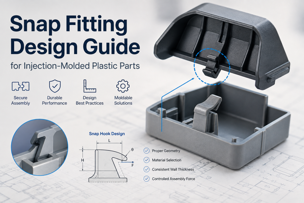
A reliable snap fit is not created by choosing an undercut depth alone. The designer must control strain at the flexible root, insertion and retention forces, tolerance stack, creep, material condition, molding orientation, tooling access, and the number of required assembly cycles. The design should then be verified in the production resin and process rather than approved from rigid CAD interference or a single 3D-printed sample.
Request a snap-fit DFM review for an injection-molded part.
What Is a Snap Fitting?
A snap-fit joint combines fastening geometry with the molded part. During assembly, a flexible arm, ring, or torsion element stores elastic energy. When the retention feature clears the mating edge, the feature recovers and engages the joint.
This simple motion creates several possible functions:
- permanent assembly that is not intended to be opened;
- serviceable assembly with a tool-access release;
- repeated manual opening and closing;
- location before screws, welding, or adhesive are applied;
- audible or tactile confirmation that assembly is complete;
- retention of covers, bezels, connectors, ducts, clips, and internal modules.
The intended function must be stated before geometry is selected. A one-time hidden clip can accept different tradeoffs from a battery door expected to survive repeated service. Likewise, a cosmetic enclosure, a fluid-adjacent component, and an under-hood assembly require different material and validation plans.
The Main Types of Snap-Fit Joints
Cantilever Snap Fits
The cantilever snap is the most common form. One end is fixed to the part and the free end carries a hook or bead. The arm bends as the lead-in face passes the mating edge, then recovers to provide retention.
Cantilever joints are easy to understand and can be placed around enclosure walls, but the fixed root is the critical stress location. Arm length, thickness, taper, root radius, hook height, width, and material modulus all affect strain and force.
Annular Snap Fits
An annular snap uses a continuous or segmented bead around a circular component. Common applications include caps, plugs, knobs, and cylindrical housings. Assembly expands one part or compresses the other until the bead engages a groove.
Annular joints can distribute retention around the circumference. They also create significant radial interference and may require careful ejection analysis. Slots can reduce stiffness and assembly force, but they may also affect sealing, strength, and appearance.
Torsional Snap Fits
A torsional snap rotates around a bar or flexible axis rather than bending mainly as a cantilever. This approach can suit latches, push tabs, and mechanisms that need a defined release motion. Stress concentrations at the torsion element and transitions must be reviewed, and the molding tool must be able to form the geometry.
U-Shaped and L-Shaped Snap Fits
Folded or offset arms can create a longer effective beam inside a limited package. These shapes may lower strain for a required hook travel, but they introduce extra corners, molding constraints, and potential weak sections. They should be evaluated as load paths, not selected only to fit the CAD envelope.
| Joint type | Best suited to | Main design risk | Tooling question |
| Cantilever | Enclosure covers, clips, tabs, connectors | High strain at the fixed root | Can the hook be formed and ejected without a trapped undercut? |
| Annular | Caps, plugs, circular housings | Excessive radial interference or assembly force | Can the bead strip from the core, or are segments/slides required? |
| Torsional | Latches and controlled-release tabs | Stress at the torsion bar and transition | Is the rotating feature supported and accessible in the mold? |
| U- or L-shaped | Compact packaging needing a longer load path | Corner stress and difficult molding geometry | Does the folded path create thin steel or an inaccessible shutoff? |
Decision: Start with the simplest joint that meets retention, service, and packaging requirements. A complex snap is justified only when it lowers functional risk or eliminates a more expensive secondary operation.
The Four Requirements Every Snap Fit Must Define
1. Required Deflection
Required deflection is the movement needed for the hook or bead to clear the mating feature during assembly. It is driven by the undercut, lead-in geometry, alignment error, and tolerance stack. More deflection generally means more strain, so the undercut should not be increased as a substitute for a proper retention analysis.
2. Insertion Force
Insertion force affects assembly equipment, operator ergonomics, part damage, and line speed. It depends on beam stiffness, lead-in angle, friction, surface texture, alignment, and the number of clips engaging at the same time. A force that feels acceptable on a hand sample may be unsuitable when several snaps engage together or when an automated fixture has limited travel control.
3. Retention and Release Force
Retention force is not the same as insertion force. It depends on the return-face angle, contact location, friction, hook engagement, material stiffness, and the direction of the applied service load. A serviceable joint also needs a release path that does not overstress the snap or encourage the user to pry against a cosmetic surface.
4. Life Requirement
State whether the joint is one-time, occasionally serviceable, or repeatedly cycled. Time under load, temperature, humidity, chemicals, UV exposure, and assembly speed can all change performance. A material that survives one room-temperature assembly may take a permanent set or crack after hot aging and repeated use.
A Practical Cantilever Snap-Fit Calculation
A simple rectangular cantilever provides a useful first screening model. For a beam of length L, thickness t, width b, elastic modulus E, and tip deflection y, small-deflection beam theory gives the approximate maximum root strain:
root strain = 1.5 x t x y / L^2
The corresponding idealized tip load is approximately:
tip load = E x b x t^3 x y / (4 x L^3)
These equations show the most important design relationships:
- increasing arm length strongly reduces strain and required load;
- increasing thickness sharply increases stiffness and insertion force;
- increasing width raises force but does not reduce the strain caused by a given deflection;
- increasing hook travel raises both deflection and root strain;
- a tapered arm can distribute strain more evenly than an abrupt constant section.
The equations are not a release-to-production calculation. They assume an ideal straight beam, small deflection, linear elastic material behavior, and a simplified end load. Real snaps include tapers, radii, hook contact, friction, large rotation, molded-in stress, anisotropy, and tolerance variation. Use the resin supplier’s time-, temperature-, moisture-, and strain-rate-relevant data, then confirm critical designs with nonlinear analysis and physical testing.
ENGINEERING DATA PLACEHOLDER: Insert one internally verified calculation example using a real but anonymized Kemal part. Record resin and grade, molded condition, arm dimensions, required travel, calculated peak strain, measured insertion force, measured retention force, conditioning, temperature, sample count, and failure mode. Do not publish invented values.
Geometry Rules That Reduce Snap-Fit Failure
Make the Flexible Length Work for You
If strain is too high, increasing the effective arm length is usually more helpful than simply making the hook smaller. Relief slots or a folded load path can increase flexibility, provided they do not weaken the surrounding wall or create a tooling problem.
Use a Generous Root Transition
An abrupt corner at the fixed end concentrates stress and can become the crack origin. Blend the arm into the supporting wall with a smooth radius and avoid a sudden thickness step. The radius must still be compatible with the mating envelope, mold machining, and local wall thickness.
Avoid an Unnecessarily Thick Arm
Because bending stiffness rises rapidly with thickness, a small thickness increase can produce a large assembly-force increase. A thick, short arm often looks strong in CAD but may be harder to assemble and more likely to exceed allowable strain.
Separate Lead-In and Retention Functions
The lead-in face should guide assembly without an abrupt force spike. The return face controls retention or release. A near-vertical return face can increase retention but may make the joint permanent or require a release tool. Select both angles from the required user and service behavior.
Control the Mating Stop
The snap should retain the assembly; it should not be the only feature that locates every direction or absorbs every service load. Add hard stops, ribs, pilots, or locating surfaces so the joint does not remain over-deflected after assembly. A controlled stop also helps manage flushness and rattle.
Provide Assembly Clearance Without Creating Rattle
The flexible feature needs space to move during assembly. The assembled product also needs a controlled gap so normal variation does not preload the snap or leave the enclosure loose. Analyze the complete stack, including both molded parts, not a nominal CAD section alone.
Keep the Snap Away From Molding Defects
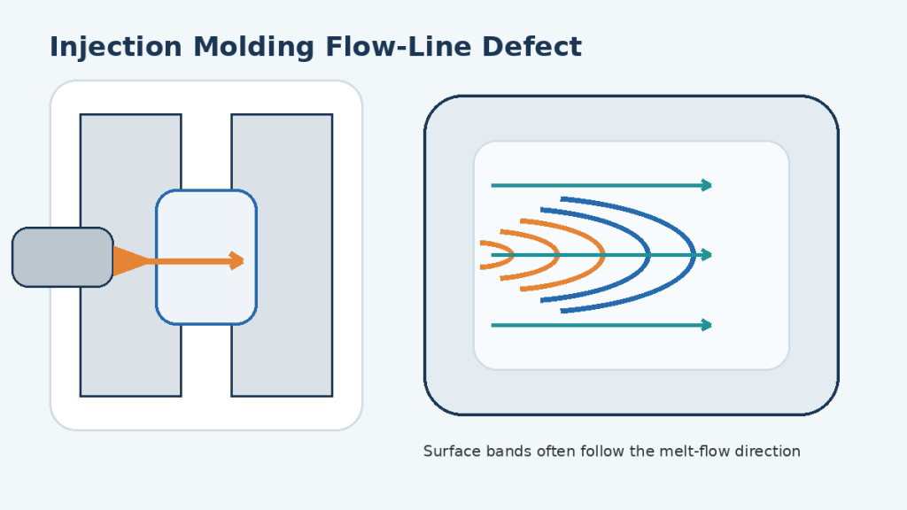
Gate location and flow direction can influence fiber orientation, weld lines, shrinkage, and residual stress. A weld line or severe flow hesitation at the flexible root can reduce durability. The snap should be included in mold-flow, gate, venting, cooling, and ejection discussions rather than added after the rest of the part is frozen.
Read Kemal’s injection molding DFM guide for the surrounding wall, rib, draft, gate, and ejection considerations.
Selecting a Plastic for Snap Fittings
Material choice should start with the required strain, retention force, cycle life, environment, and dimensional stability. Generic resin-family descriptions are only a screening tool; the final design needs grade-specific data.
| Material family | Why designers consider it | Main cautions for snap fits |
| Polypropylene (PP) | Low density, good toughness, useful flex-fatigue behavior in suitable grades | Creep, temperature dependence, shrinkage, and lower stiffness can reduce long-term retention |
| Polyamide (PA/nylon) | Toughness, fatigue resistance, strength, and wear performance | Moisture changes dimensions and mechanical behavior; conditioning state matters |
| Acetal (POM) | Low friction, dimensional stability, fatigue and wear performance | Grade-specific environmental limits, notch sensitivity, and joining/finishing constraints |
| Polycarbonate (PC) | Toughness and useful stiffness for housings and latches | Chemical stress cracking, molded-in stress, and environment must be checked |
| ABS | Common enclosure material with good appearance and processability | Repeated flexing and low-temperature impact depend on grade and geometry |
| PC/ABS | Balance of toughness, processability, and enclosure performance | Blend ratio, chemicals, temperature, and flame-retardant grade can change behavior |
| Elastomeric materials | Soft engagement, damping, sealing, and reduced rattle | Low stiffness may not provide enough retention; creep and overmold adhesion can dominate |
Fillers can increase stiffness and change shrinkage, but they may reduce strain capability and make orientation more important. Recycled content, colorant, flame retardant, UV package, and supplier changes can also affect a snap’s performance. The approved material specification should therefore identify the exact grade and permitted changes.
Use the injection molding material selection guide to narrow candidates, then validate the selected grade in the actual molded geometry.
Tolerance and Clearance Planning
There is no universal snap-fit clearance that works for every plastic and part size. The functional stack can include:
- shrinkage variation in both mating parts;
- mold steel and process variation;
- warpage and sink near the snap or window;
- material moisture and temperature expansion;
- paint, texture, plating, labels, seals, or secondary operations;
- assembly fixture alignment;
- the engagement of multiple snaps at once.
Analyze at least three states:
- Worst-case assembly: Can the snap clear the mating edge without exceeding the allowed strain or assembly force?
- Worst-case retention: Does the minimum engagement still meet pull-off, shear, and vibration requirements?
- Worst-case appearance: Are flushness, gap, squeak, and rattle acceptable without leaving the snap permanently loaded?
Statistical tolerance analysis may be useful for stable high-volume processes, but it should not hide a hard interference or a safety-related minimum engagement. Critical dimensions should have an agreed measurement method and conditioning state.
Injection Mold Tooling Considerations
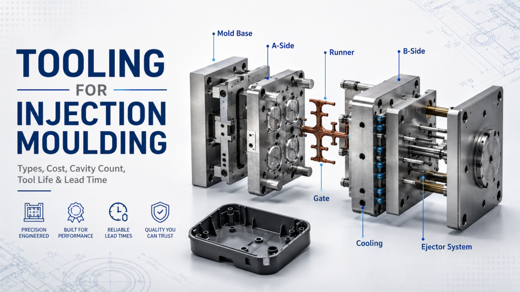
A snap can function perfectly in CAD and still be expensive or impossible to mold. Review the hook, opening, and release direction together with the mold parting line.
Undercut Formation
Some flexible hooks can strip from the core during ejection if the resin, geometry, temperature, and ejection support permit it. Other designs need a slide, lifter, collapsible feature, or redesign. Forced stripping should never be assumed without checking strain during ejection and the risk of whitening, tearing, or permanent deformation.
Draft and Shutoffs
Non-contact faces generally need draft appropriate to texture, depth, resin, and tool construction. Shutoff surfaces need enough angle and steel strength to resist wear and flash. A narrow slot beside a snap can create fragile mold steel or difficult venting.
Gate, Cooling, and Ejection
Gate location should support balanced filling around the snap and avoid a weak weld line at the root. Uneven cooling can warp the mating wall and change engagement. Ejector placement must support the part without bending the snap or marking a functional surface.
Steel-Safe Adjustment
Where practical, design the tool so hook engagement, window size, or stop position can be adjusted by removing steel rather than welding it back. This does not replace tolerance analysis, but it can make production tuning more controlled.
For early tool review, see Kemal’s mold design services.
MID-ARTICLE CTA: Have a snap hook, mating window, or enclosure assembly reviewed before tooling. Send the CAD, resin grade, cycle requirement, and target forces to Kemal for DFM discussion.
Common Snap-Fit Failures and Corrective Actions
| Failure | Likely causes | What to check first | Possible corrective direction |
| Crack at the arm root | Excessive strain, sharp transition, brittle grade, weld line, molded-in stress | Root radius, required travel, material condition, gate/flow pattern | Increase effective length, smooth transition, reduce travel, review resin and gate |
| White stress mark after assembly | Local yielding, high impact speed, sharp contact, ejection damage | Assembly motion, peak deflection, hook contact, part temperature | Lower strain and force spike; improve lead-in and support |
| Insertion force too high | Arm too stiff, steep lead-in, high friction, simultaneous engagement, misalignment | Force curve and the order in which clips engage | Lengthen or taper arm, revise lead-in, add pilots, sequence engagement |
| Retention too low | Insufficient engagement, creep, warpage, shallow return face, tolerance loss | Minimum engagement after conditioning and aging | Correct stack, add stop/support, revise hook or material |
| Snap does not recover | Plastic deformation, creep, hot assembly, unsupported preload | Residual deflection over time and temperature | Reduce sustained strain; add hard stop; choose grade from long-term data |
| Snap breaks after service cycles | Fatigue, user over-travel, notch, chemical exposure | Cycle count, release method, environment, fracture origin | Add travel limit, improve radius, reduce cyclic strain, validate environment |
| Rattle or visible gap | Excess clearance, weak locating features, tolerance stack, deformation | Assembly datums, hard stops, minimum preload | Separate locating and retention; revise stops and stack |
| Mold or ejection damage | Trapped undercut, inadequate draft, thin steel, unsupported stripping | Tool opening and ejection simulation | Add slide/lifter, change parting line, revise hook or opening |
Decision: Do not fix every snap problem by enlarging the hook. A larger undercut can improve nominal engagement while increasing assembly strain, tool complexity, and failure risk. Identify whether the root cause is load path, tolerance, material, molding, or user behavior first.
Prototype Strategy: What Each Process Can Prove
| Prototype route | What it can help evaluate | What it may not reproduce |
| 3D printing | Packaging, access, assembly sequence, interference, early user feedback | Molded-resin properties, flow orientation, weld lines, shrinkage, surface friction, production fatigue life |
| CNC machining | Mating geometry, rigid interfaces, dimensional stack in machinable materials | Thin molded flexures, molded-in stress, gate effects, exact snap behavior |
| Vacuum casting | Small batches and flexible geometry in cast polyurethane systems | Exact production-resin creep, moisture behavior, shrinkage, and fiber orientation |
| Prototype injection molding | Production-like resin, gating, shrinkage, assembly force, molded failure modes | Full production-cavity balance or long-term field life without a defined validation plan |
Use rapid prototypes to answer the questions they can answer. Final approval should use the specified resin, representative tooling and process, correct conditioning, and a test plan tied to the product requirement.
Kemal’s plastic rapid prototyping and prototype injection molding pages explain two routes for staged validation.
How to Validate a Snap-Fit Joint
A pass/fail assembly check is not enough for a critical snap. Define measurable acceptance criteria before testing.
Dimensional Inspection
Measure the features that control function: arm thickness and length, hook height, mating-window position, hard-stop location, wall flatness, and assembled gap. Agree on the datum system, part conditioning, and measurement fixture.
Force-Displacement Testing
Record insertion and removal or release force against travel. A force-displacement curve can reveal a sharp interference spike, multiple clips engaging out of sequence, incomplete recovery, or excessive friction. Report test speed and fixture alignment because both can affect the result.
Cycle and Abuse Testing
Cycle the joint to the required service life, including foreseeable over-travel or off-axis use where appropriate. Inspect for cracks, whitening, permanent set, retention loss, and damage to the mating feature.
Environmental Conditioning
Condition parts for relevant temperature, humidity, fluid, cleaner, UV, and aging exposure. Test both immediately after conditioning and after any specified recovery period. Nylon moisture state and long-term creep at elevated temperature are examples of conditions that can change conclusions.
Production Process Validation
Confirm performance across the intended molding window and representative cavities, lots, and material conditions. A snap that passes only on the first carefully tuned samples may not be robust enough for normal production variation.
Use a clear inspection and test record linked to part revision, resin lot, molding condition, sample number, and test condition. Review Kemal’s quality assurance approach when defining project records.
Snap Fit vs Screws, Welding, and Adhesive
| Joining method | Main advantages | Main limitations | Best fit |
| Integral snap fit | Fast assembly, no loose fastener, potential automation, easy part-count reduction | Geometry and material sensitive; creep, fatigue, tooling undercuts, tamper/service limits | High-volume plastic assemblies with controlled loads |
| Screws | Defined clamp load, familiar service method, broad material compatibility | Added parts, bosses, torque control, assembly time, potential strip-out | Serviceable products or joints needing clamp force |
| Ultrasonic or other plastic welding | Permanent sealed joint, no visible fastener, fast cycle when developed | Equipment and fixture cost, particulate/marking risk, not normally serviceable | Permanent housings with compatible materials and joint design |
| Adhesive | Joins dissimilar materials and distributes load | Cure time, surface preparation, chemicals, process control, rework limits | Sealing or joints unsuitable for integral features |
A hybrid design is often appropriate. Snaps can locate parts and hold them for screws or welding, while hard stops and other features carry service loads. Select the joining method from function, service, environment, appearance, automation, and total manufacturing cost rather than fastener count alone.
RFQ Checklist for an Injection-Molded Snap-Fit Part
Provide the following information for a useful DFM and quotation review:
- 3D CAD for both mating parts
- Controlled 2D drawings and revision
- Resin manufacturer, exact grade, color, filler, and approved alternatives
- One-time, serviceable, or repeated-cycle requirement
- Target insertion, retention, and release forces
- Assembly direction, speed, fixture, and operator constraints
- Service loads and where they enter the joint
- Operating temperature, humidity, chemicals, UV, vibration, and aging
- Gap, flushness, rattle, cosmetic, and audible-click requirements
- Required dimensional and force-test records
- Prototype and production quantities
- Tool-life, cavity, lead-time, packaging, and delivery requirements
- Photos or samples of any existing crack, whitening, loose fit, or assembly issue
The quote package should distinguish assumptions from confirmed requirements. If target forces, cycle life, or environmental conditions are unknown, identify them as development items rather than allowing the mold to become the first test.
Frequently Asked Questions
Is “snap fitting” the same as a snap-fit joint?
In plastic product design, the phrases usually refer to the same fastening concept. “Snap-fit joint” or “snap fit” is the more common engineering term. “Snap fitting” can be ambiguous outside this context, so drawings and specifications should name the joint type and function.
What is the best plastic for a snap fit?
There is no universal best resin. Choose from grade-specific strain capability, modulus, creep, fatigue, temperature, moisture, chemicals, UV, flammability, appearance, and molding requirements. PP, PA, POM, PC, ABS, and PC/ABS can all be appropriate in different designs.
How much undercut should a snap fit have?
Undercut must come from the required retention and the allowable assembly strain, not a universal rule. Calculate the required deflection at worst-case tolerance, check insertion and retention forces, and confirm performance in the production material and condition.
Can a snap fit be opened repeatedly?
Yes, if the geometry includes a safe release path and the material, strain, travel limit, and environment support the required cycle life. A one-time hidden hook should not be assumed to work as a service latch.
Why does a plastic snap turn white?
Stress whitening can indicate localized high strain, impact, yielding, or micro-damage. Check the root, lead-in contact, required travel, assembly speed, material condition, and ejection history. A white mark is a symptom, not the root cause.
Can 3D-printed snap fits validate an injection-molded design?
They can validate packaging, access, assembly direction, and early geometry. They usually do not reproduce molded-resin properties, flow orientation, weld lines, shrinkage, residual stress, or long-term creep. Use molded samples for final functional approval.
Does every snap-fit undercut require a mold slide?
No. Some geometries can be formed in the mold opening direction, some can flex during ejection, and others require slides or lifters. The decision depends on the resin, strain during ejection, hook direction, draft, support, surface requirements, and tool life.
How should snap-fit quality be inspected?
Combine critical dimensional checks with functional force-displacement, retention, cycle, and environmental testing. Record the part revision, resin lot, molding condition, sample conditioning, fixture, test speed, and acceptance limits.
Final Takeaway
A successful snap fitting is a controlled elastic system, not simply a hook added to a wall. Define deflection, force, retention, life, environment, tolerance, and service behavior first. Then align material data, beam geometry, mating stops, mold construction, process variation, and validation to those requirements.
For an engineering review, send Kemal both mating CAD files, the resin grade, target forces, cycle requirement, and expected environment.