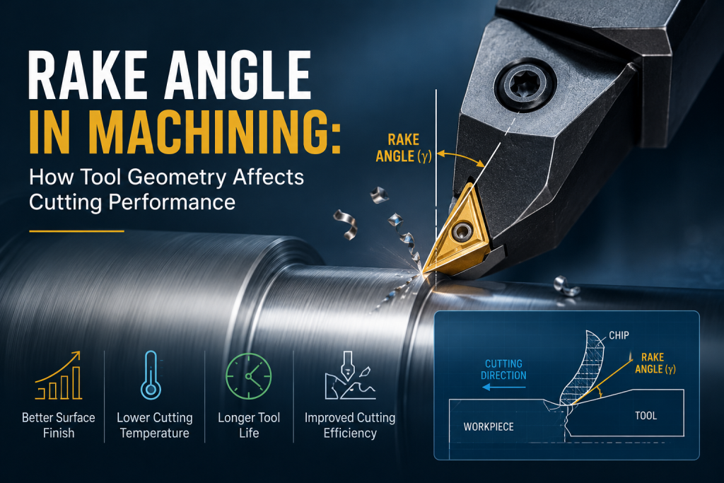
Rake angle is a key cutting-tool geometry that affects how the tool removes material and how chips flow across the cutting edge. It directly influences cutting force, heat, tool strength, chip control, and surface finish.
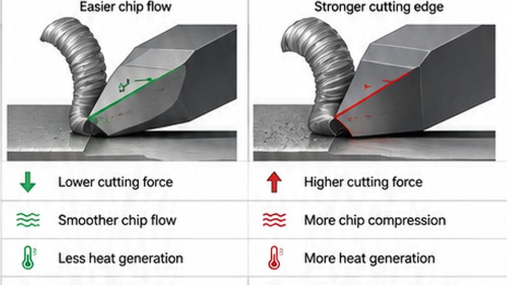
In general, a positive rake angle provides sharper cutting and lower cutting forces, while a negative rake angle strengthens the cutting edge but requires greater force and machine rigidity.
This guide explains positive, zero, and negative rake angles and how to select suitable tool geometry for different materials and machining conditions.
What Is Rake Angle?
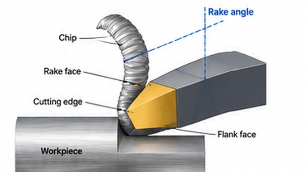
Rake angle is the angle that describes the orientation of a cutting tool’s rake face relative to the workpiece and cutting direction. The rake face is the surface over which the chip flows after material is separated by the cutting edge.
In a simplified orthogonal cutting model, the tool has three important geometric elements:
- The cutting edge, which separates material from the workpiece.
- The rake face, over which the newly formed chip moves.
- The flank face, which faces the newly machined surface.
The orientation of the rake face determines whether the tool has a positive, zero, or negative rake angle. A more positive rake tends to make cutting easier, whereas moving toward a negative rake increases the wedge of material supporting the cutting edge.
Positive, Zero, and Negative Rake Angles
| Rake Type | Cutting Edge Character | Cutting Force | Edge Strength | Typical Advantage |
| Positive rake | Sharper cutting action | Lower | Lower | Easier cutting and lower forces |
| Zero rake | Intermediate | Moderate | Moderate | Balance between cutting action and support |
| Negative rake | Stronger/blunter edge | Higher | Higher | Strong edge for demanding cuts |
These are general tendencies rather than fixed rules. Actual machining performance also depends on insert geometry, edge preparation, tool material, workpiece material, cutting speed, feed, depth of cut, coolant, and machine rigidity.
Positive Rake Angle
A positive rake angle positions the rake face so that the cutting wedge becomes relatively sharp. It generally reduces cutting forces and power requirements, encourages chip flow, and can reduce deflection in less rigid setups. The trade-off is cutting-edge strength: as the rake becomes more positive, less material supports the edge, making it potentially more vulnerable to chipping under interrupted or heavy cutting conditions.
Zero Rake Angle
At approximately zero rake, the tool face provides an intermediate geometry between positive and negative configurations. It does not provide the same sharp cutting action as a strongly positive geometry or the same edge reinforcement associated with a strongly negative geometry.
Negative Rake Angle
A negative rake angle increases the material supporting the cutting edge. It can improve edge strength and resistance to failure under heavy loads or interrupted cutting, but it normally increases cutting force and power demand. The machine, toolholder, workholding, and workpiece must therefore provide enough rigidity.
How Rake Angle Affects the Machining Process
1. Cutting Force
Increasing rake angle generally reduces the force required to form and move the chip. This can matter when machining thin walls, slender shafts, small features, delicate workpieces, or setups with long tool overhang. Lower cutting force does not mean the largest possible positive rake is always best, because increasing positive rake also reduces support behind the cutting edge.
2. Chip Formation and Evacuation
Rake geometry influences chip flow direction, chip thickness, tool-chip contact, chip curling behavior, and friction between the chip and tool. A positive rake tends to make chip flow easier, while increasingly negative rake geometry can increase chip compression and cutting resistance. Modern inserts also use chipbreakers, grooves, honed edges, and other microgeometry, so chip control depends on the complete insert geometry.
3. Cutting-Edge Strength
The relationship between rake angle and cutting-edge strength creates one of the central trade-offs in tool selection. A larger positive rake creates a sharper wedge but leaves less tool material directly behind the edge. Moving toward negative rake creates a thicker wedge with more support.
4. Heat and Friction
Machining generates heat through material deformation and friction at the tool-chip and tool-workpiece interfaces. Because rake angle changes chip formation, contact conditions, and cutting forces, it can also change the thermal load in the cutting zone. Rake angle should therefore be considered together with cutting speed, feed, depth of cut, coolant strategy, coating, insert grade, and workpiece material.
5. Surface Finish
Rake angle can indirectly influence surface quality by changing cutting force, chip behavior, built-up edge tendency, vibration, and tool deflection. However, poor surface finish should not automatically be diagnosed as a rake-angle problem. Feed rate, speed, nose radius, edge wear, runout, chatter, tool overhang, workholding rigidity, and coolant delivery may be equally important.
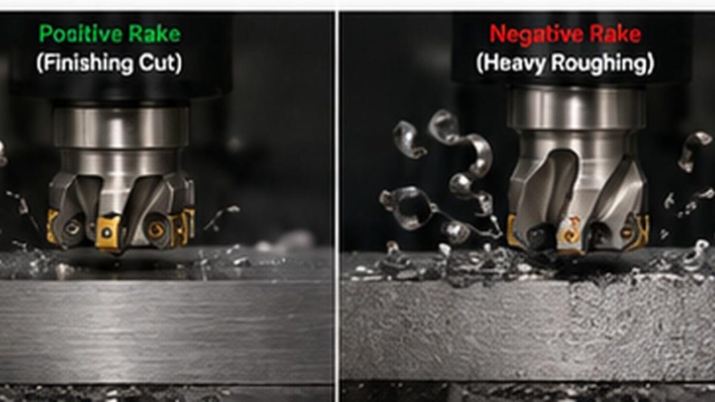
Positive vs. Negative Rake Angle: Which Is Better?
Neither is inherently better. The appropriate geometry depends on whether the machining operation needs to prioritize easier cutting or stronger edge support.
| Machining Requirement | General Rake Direction to Consider |
| Reduce cutting forces | More positive |
| Machine a flexible or thin-wall part | More positive |
| Promote easier chip flow | More positive |
| Reduce deflection in a light setup | More positive |
| Increase cutting-edge strength | More negative |
| Heavy roughing | More negative |
| Interrupted cutting | More negative |
| Stable, rigid machining conditions | Can support more negative geometry |
These are selection tendencies, not universal specifications. Insert manufacturers often combine macrogeometry and microgeometry to obtain a particular cutting behavior.
How Rake Angle Changes with Workpiece Material
Aluminum and Other Ductile Materials
Aluminum alloys can generate long chips and may adhere to the cutting edge under unsuitable conditions. Sharp cutting edges and positive rake geometries are commonly used to lower cutting forces, promote chip evacuation, reduce smearing, and limit built-up edge. The exact geometry still depends on alloy, operation, parameters, and cutter design.
Steel
Steel covers a wide range of compositions and hardness levels. Finishing may benefit from relatively sharp cutting geometries, while stable roughing may use stronger edges capable of carrying higher loads. Consider grade, hardness, heat treatment, depth of cut, interrupted cutting, and machine rigidity.
Stainless Steel
Many stainless steels combine work-hardening behavior with relatively poor thermal conductivity. Suitable positive geometries can help reduce cutting forces and rubbing, but the edge must remain strong enough for the operation. Tool wear, coolant delivery, chip control, and cutting parameters are especially important.
Cast Iron
Many cast irons produce shorter chips than ductile materials. Depending on grade and operation, stronger cutting-edge geometries can be appropriate, while abrasive wear may become an important tool-selection factor.
Titanium Alloys
Titanium machining places high thermal and mechanical demands near the cutting edge. Tool geometry must balance cutting sharpness with adequate edge strength and should be selected together with cutting speed, coolant strategy, engagement, tool grade, and edge preparation.
Engineering Plastics
Plastics generally require sharp cutting tools and low cutting forces to reduce deformation, rubbing, and excessive heat. Positive rake geometries are therefore common, although reinforced, brittle, or heat-sensitive plastics may require different edge designs.
Rake Angle in Turning, Milling, and Drilling
Turning
In turning, insert geometry and its orientation in the toolholder determine how the cutting edge interacts with the rotating workpiece. Different geometries may be used for roughing, finishing, grooving, threading, and boring. In internal turning, tool overhang and bore diameter can make cutting-force control especially important.
Milling
A milling cutter contains multiple cutting edges, so effective geometry depends on both the insert and the cutter body. Rake characteristics may be described in axial and radial directions. Positive milling geometry can reduce cutting forces for thin walls or less rigid setups, while stronger geometries may be selected when stability and edge durability are more important.
Drilling
Drill geometry is more complex because effective rake angle changes along the cutting edge. Conditions near the outer cutting edge differ significantly from those near the drill center, which is why drilling performance cannot be explained by a single rake-angle value.
Rake Angle vs. Clearance Angle
Rake angle controls the orientation of the surface over which the chip flows. Clearance angle helps prevent the flank of the tool from rubbing excessively against the newly machined surface.
| Tool Angle | Main Function |
| Rake angle | Influences cutting action, chip formation, force, and edge strength |
| Clearance angle | Provides clearance between the tool flank and machined surface |
| Cutting-edge/wedge geometry | Determines the physical support behind the cutting edge |
Both must work together. Increasing one geometric angle can change the material supporting the cutting edge, so tool geometry is normally designed as a complete system.
Rake Angle vs. Relief Angle
In many machining contexts, relief angle and clearance angle describe closely related geometric concepts: providing space behind the cutting edge so the tool does not rub against the machined surface. Rake angle acts on the chip side of the cutting edge, whereas relief or clearance geometry primarily affects the flank side.
How to Choose an Appropriate Rake Angle
Start with the Workpiece Material
Determine whether the material is ductile or brittle, soft or hardened, abrasive, prone to work hardening, likely to form a built-up edge, or sensitive to machining heat.
Consider the Operation
Roughing and finishing impose different requirements. Heavy roughing puts more load on the cutting edge, while finishing often emphasizes low cutting forces, dimensional stability, and surface quality.
Evaluate Rigidity
Machine rigidity, workholding, toolholder stiffness, and tool overhang affect how much cutting force the system can tolerate. A strong negative-rake insert may survive heavy loads, but the resulting forces can still cause deflection, chatter, or dimensional error.
Consider the Complete Tool Geometry
Do not select a tool from nominal rake angle alone. Also evaluate insert shape, edge preparation, chipbreaker, nose radius, clearance geometry, cutting-edge radius, coating, and tool material.
Troubleshooting Machining Problems Related to Tool Geometry
Excessive Cutting Force
Possible contributors include rake geometry that is too negative for the setup, a worn edge, excessive feed or depth of cut, unsuitable tool geometry, or poor chip evacuation. Moving toward a sharper geometry may reduce force if adequate edge strength remains.
Burr Formation
Burrs can result from material deformation near the workpiece edge rather than clean shearing. Dull edges, unsuitable geometry, cutting direction, tool wear, and inappropriate feeds and speeds can all contribute.
Poor Surface Finish
Check cutting-edge condition, chip evacuation, built-up edge, cutting speed and feed, toolholder and workpiece rigidity, runout, tool overhang, and coolant delivery before attributing the problem to rake angle.
Chatter or Workpiece Deflection
Reducing cutting force through a more positive geometry can sometimes improve stability for thin walls, slender features, or long overhangs. Chatter can also originate from spindle speed, engagement, fixturing, or structural dynamics.
Why Rake Angle Matters in CNC Part Design
Product designers normally do not specify rake angle on a component drawing because rake angle belongs to the manufacturing tool rather than the finished part. However, part geometry determines what tools can physically reach the required features and how rigid the cutting setup can be.
- Deep pockets
- Narrow grooves
- Small internal radii
- Deep bores
- Thin walls
- Tall ribs
- Restricted tool access
These features may force the machinist to use smaller, longer, or less rigid tools. Under these conditions, cutting force and tool geometry become increasingly important. A machining problem that appears to be caused by the cutting tool can therefore originate in part geometry or tool accessibility.
For a broader overview of CNC processes, materials, design considerations, and manufacturing options, see Kemal’s CNC machining capabilities and guide.
Practical Example: Thin-Wall CNC Machining
Consider an aluminum housing with a thin vertical wall. During milling, excessive radial cutting force can push the wall away from the cutter. After the cutter passes, the wall springs back, potentially creating dimensional error or an inconsistent surface.
A sharper, more positive cutting geometry may reduce cutting pressure, but changing rake geometry alone may not solve the problem. The machining engineer may also need to adjust radial engagement, axial depth, finishing allowance, tool diameter, tool overhang, cutting direction, fixture support, and toolpath sequence.
Key Takeaways
- Positive rake angles create a sharper cutting action and generally reduce cutting forces.
- Negative rake angles provide greater support behind the cutting edge but usually increase cutting forces.
- Zero rake represents an intermediate geometry.
- Material properties, operation type, rigidity, chip control, and edge preparation should be considered together.
- Rake angle can influence surface finish and burr formation, but it should not be treated as the cause of every machining problem.
The most useful question is not simply “What rake angle should I use?” but “What combination of tool geometry and cutting conditions best suits this material, feature, and setup?”
If a CNC-machined part is experiencing persistent burrs, poor surface finish, thin-wall deformation, difficult chip evacuation, or limited tool accessibility, submit the part drawing or CAD model, material specification, quantity, critical tolerances, surface-finish requirements, and problematic features for a manufacturability and machining-process review.
View Kemal CNC Machining Capabilities
Frequently Asked Questions
What is rake angle in machining?
Rake angle describes the orientation of the cutting tool’s rake face, the surface over which the chip flows. It affects cutting force, chip formation, cutting-edge strength, and overall machining behavior.
What does a positive rake angle do?
A positive rake generally creates a sharper cutting action, lowers cutting forces and power requirements, and can promote easier chip flow. The trade-off is reduced material supporting the cutting edge.
What does a negative rake angle do?
Negative rake increases support behind the cutting edge and can improve edge strength under demanding cutting conditions. It generally produces higher cutting forces and requires a sufficiently rigid machining setup.
Does increasing rake angle reduce cutting force?
Generally, yes. A more positive rake tends to reduce cutting resistance, although the effect depends on material, complete tool geometry, cutting conditions, and lubrication.
Is positive rake always better for surface finish?
No. Positive rake can reduce cutting forces, but surface finish also depends on feed, speed, nose radius, tool wear, runout, rigidity, vibration, chip evacuation, and built-up edge.
What is the difference between rake angle and clearance angle?
Rake angle primarily influences chip formation and cutting behavior on the rake-face side of the tool. Clearance angle creates space between the tool flank and the newly machined surface to reduce rubbing.
Which rake angle should be used for aluminum?
Positive and sharp cutting geometries are commonly used for aluminum because they can reduce cutting resistance and support chip evacuation. The appropriate geometry still depends on the alloy, operation, machine rigidity, tool type, and cutting conditions.
Can rake angle cause burrs?
Rake geometry can influence burr formation because it changes how material deforms and separates at the cutting edge. Tool wear, cutting direction, feeds and speeds, edge condition, and part geometry can also be important.