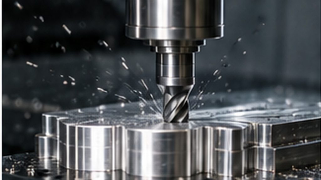
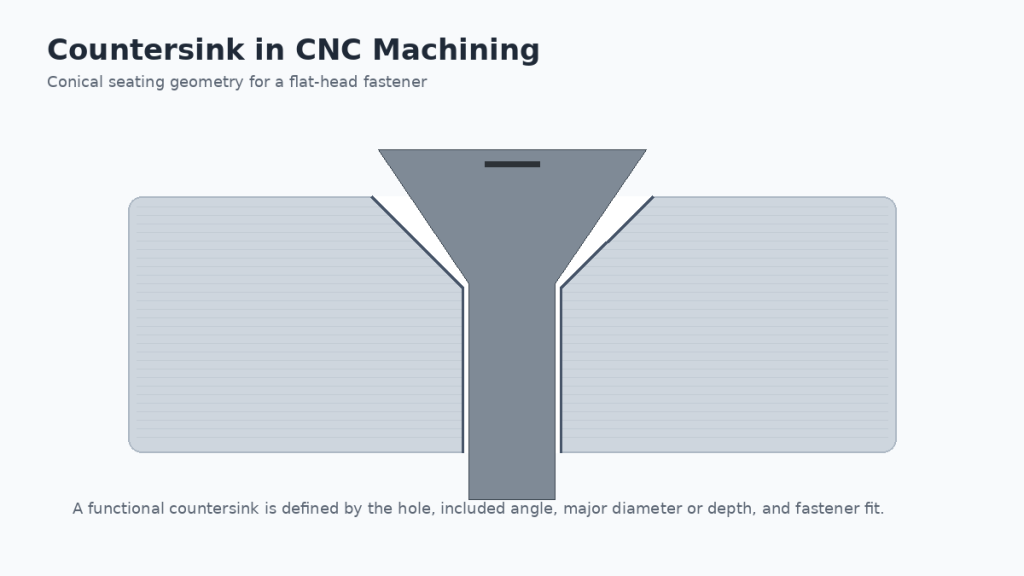
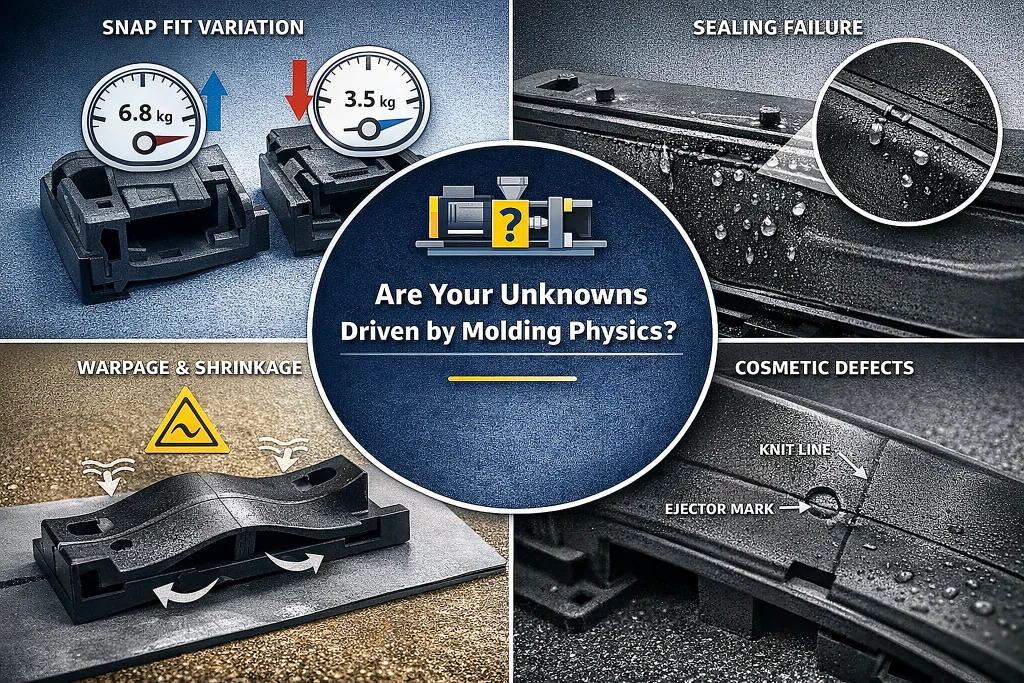
A single 3D-printed or CNC part may fit and function. Once you validate under production-like conditions, including small-batch builds, snap cycling, sealing checks, and heat and humidity exposure, variation starts to show up. Fit shifts. Snap force variation widens. Sealing can fail locally. Cosmetic witness marks may land on surfaces you cannot accept.
This is rarely a CAD problem. It is normal molding behavior. Shrinkage, warpage, and process window variation move the part away from nominal.
Ask one question. Are your remaining unknowns driven by molding physics? If yes, you need molded parts to learn. More 3DP or CNC parts will not be representative.
What are you actually trying to validate?
Most switching decisions get stuck because the team argues about processes. You will get a clearer answer if you first name the validation target.
Prototype work usually moves through three stages. Each stage asks a different question, so the “best method” changes.
Stage 1: Form and basic assembly proof
Here you are proving geometry.
Does it fit the envelope? Does it clear nearby parts? Does the assembly sequence make sense? In this stage, 3D printing is often the fastest way to learn, because you are not trying to predict molded behavior yet.

Stage 2: Functional proof
Now the part must take the load. It must move. It must survive repeated use.
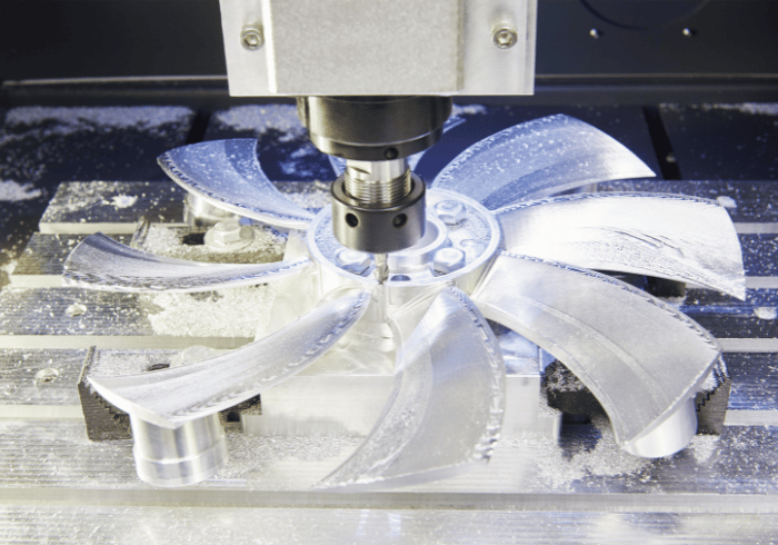
CNC machining can work well here, especially when you can machine a material that is close to your target resin, and the geometry is machining-friendly.
But be careful when the function depends on molding results. Snap feel, fatigue life, sealing shutoffs, and cosmetic constraints can change once shrinkage and warpage enter the picture. CNC can confirm the geometry, but it may not predict the molded outcome.
Stage 3: Production intent proof
This is the point where you stop asking “does it work” and start asking “will it stay stable in molding.”
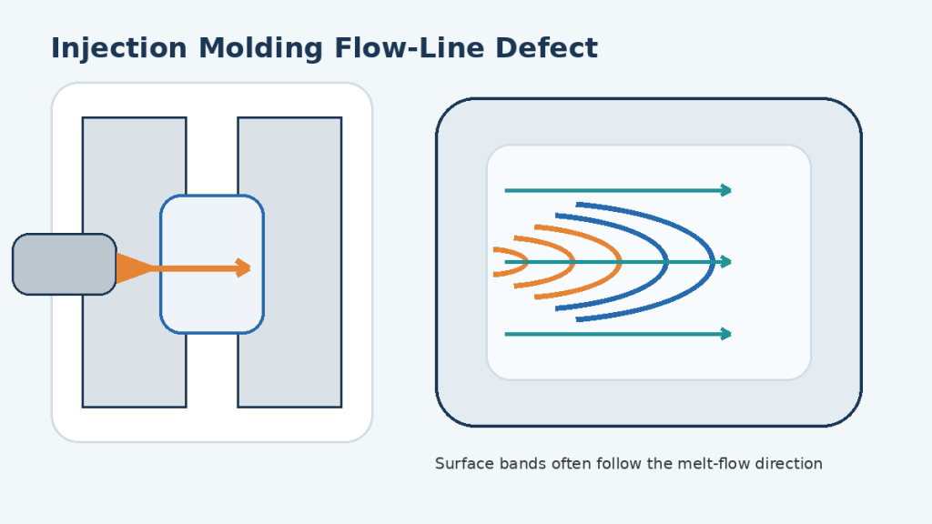
You need to see shrinkage and warpage in the actual resin. You need to see where the knit lines, parting lines, gate vestiges, and ejector witness marks land. You also need to see batch variation, not a single best part.
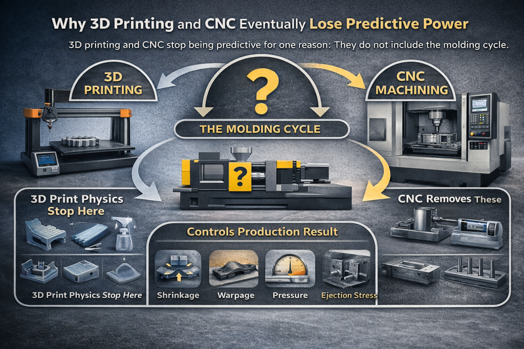
At this stage, 3D printing and CNC often stop being predictive, because the part has not gone through the molding cycle.
The practical rule is simple. When your goal changes from “one part works” to “a batch works consistently,” you are moving into production intent validation. That is when switching starts to make sense.

Why 3D Printing and CNC Eventually Lose Predictive Power
3D printing and CNC stop being predictive for one reason. They do not include the molding cycle.
What 3D printing is great at, and where it stops
3D printing moves fast. It helps you lock in geometry and assembly direction early.
But the part you print carries its own physics. Build orientation matters. Layer bonding matters. Surface finish and post-processing matter.
So you can confirm that the design can work.
You usually cannot predict how it will behave once it is molded, especially for snap force spread, fatigue life, and batch stability. Those outcomes are shaped by molding shrink and warpage, not by print layers.
CNC has the opposite problem
CNC gives you clean geometry and high repeatability. That is useful.
But it also removes the two things that dominate molded outcomes: shrink distribution and cooling-driven warpage.
A molded part does not end at the CAD nominal. It ends at the result of the molding cycle.
Material fills the cavity, pressure packs the part, cooling locks in the shrink, and ejection releases stress. Wall thickness, flow length, and gate location change that history. The same “nominal” feature can end up with different local shrinkage and different internal stress. That is why warpage and dimensional drift show up as a repeatable pattern.
The failure pattern is predictable for a reason
You have probably seen it. A CNC housing is flat and fits. The molded version lifts at one corner. A machined snap feels perfect. The molded snap shows a wider force range. One batch is tight. Another batch is loose.
That is rarely bad CAD.
It is simply the first time your validation includes molding history. Until you test molded parts, you are not validating the physics that will control production.
When Switching Becomes Necessary
The decision usually becomes clear when you hit two or three of the signals below.
Signal 1: You are validating a batch, not a single part
A single prototype can look perfect. However, once you move into multi-unit assemblies, cycling, customer samples, or a pilot build, you are validating consistency.
You start caring about spread, not just pass or fail.
Fit has a range. Snap force has a range. Sealing becomes a percentage, not a yes or no.
At that point, you need a process that naturally produces variation the same way production does. Prototype molding shows whether your variation stays inside a usable window.
Signal 2: The material must be production-equivalent
If your target resin is modified, the prototype method matters even more.
Glass-filled grades change, shrink, and become stiffer. Flame-retardant packages can change flow and knit-line strength. Chemical-resistant and high-temperature resins often narrow the process window.
“Close enough” materials and printing resins rarely behave the same way after molding. If material behavior is part of the risk, you need molded samples in the actual resin family, not approximations.
Signal 3: Your CTQs are shaped by molding physics
Some CTQs are geometry-driven. Others are molding-driven. If your CTQs fall into the second group, switching is usually unavoidable.
Common examples are:
- Sealing and mating surfaces that depend on flatness, compression stability, and flash control
- Snap and flex features where force and fatigue depend on orientation, knit lines, and local shrink
- Cosmetic requirements where gate, parting, ejector, and knit lines must land in allowed areas
These issues do not get solved by tightening a nominal dimension. They get solved by controlling shrink, warpage, and feature sensitivity to process variation.
Signal 4: Your next step makes rework expensive
If you are about to cut bridge or production tooling, or you need to ship customer samples, you cannot afford false confidence. Late discovery costs weeks.
At this stage, prototype molding is not “a nicer prototype.” It is a risk filter. It should tell you early what production will do to the part: the warpage mode, where knit lines will land, whether cosmetic constraints are solvable, and whether sealing boundaries are sensitive to flash.
The practical rule is:
Pay attention to how your team talks. If the discussion has moved from “is the CAD right” to “what will molding do to it, and can we control it,” you are already in the molding world. That is when switching becomes necessary.
Differences between 3D printing, CNC, and prototype molding
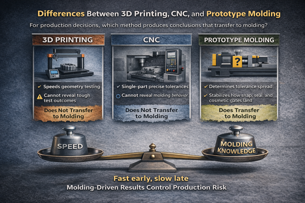
If you compare only “speed,” 3D printing wins. If you compare only “single-part precision,” CNC often wins. But for production decisions, the real question is: Which method produces conclusions that transfer to molding?
- 3D printing accelerates geometry decisions, but its anisotropy and resin mismatch make durability and batch conclusions unstable.
- CNC gives you tight geometry control, but it won’t reveal shrink, warpage, cosmetic marks, and process-window sensitivity.
- Prototype injection molding trades first-part speed for production-intent learning: the part experiences molding physics, so your risk assessment becomes transferable.
This is why many programs feel “fast early, slow late.” It’s not inefficiency. It’s a method mismatch in late-stage validation.
Why Prototype Molding Gets Expensive or Slow, and What You Can Control Early
Prototype injection molding cost and lead time are driven by three buckets.
First is the prototype tool build. Second is the number of trial-and-tune loops needed to hit your CTQs. Third is the molding time for the quantity you need. In most prototype programs, the biggest swings come from tooling complexity and iteration, not from running more cycles.
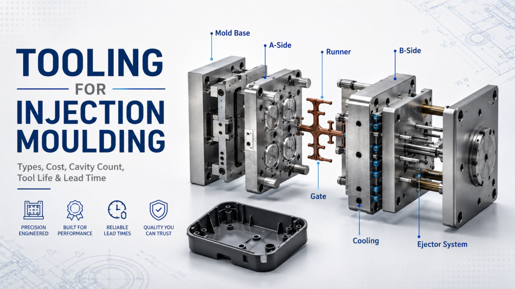
When the part has a stable pull direction and adequate draft, the tool is simpler to build and easier to tune. Gate, venting, and ejection can be placed where they work best. The process window stays wider. You typically get closer to the target on the first shots, and each iteration is more effective.
Cost and schedule start to expand when the design reduces tooling options or narrows the process window. The same few patterns show up again and again:
Undercuts and side actions
Undercuts are not just “extra geometry.” They often require slides, lifters, or complex shutoffs. Those mechanisms add machining time and fitting time. They also add flash risk at shutoff surfaces, which increases tuning effort.
Sealing boundaries and shutoff sensitivity
Sealing features can look straightforward in CAD, but they are sensitive in molding. Small changes in venting, clamp, or shutoff contact can create local flash or local leak paths. That tends to drive additional trials and tool touch-ups.
Cosmetic constraints that limit gate, parting line, and ejection choices
Cosmetic requirements become expensive when they remove the toolmaker’s degrees of freedom. If gate marks, parting lines, or ejector witness must avoid large areas, the tool strategy becomes constrained. You may need alternative gating, more complex ejection, or stricter process control, which increases both build complexity and tuning time.
Thin walls and warpage sensitivity
Thin walls and long flow lengths tighten the process window. Packing becomes less forgiving, cooling becomes less uniform, and warpage modes become more sensitive to small parameter changes. That often increases the iteration count because you are tuning for both dimensions and the deformation mode.
Abrasive or high-temperature resins
Glass-filled and high-temperature resins change stability and wear. They can widen variability if the window is narrow, and they can increase tool wear at gates and shutoffs. Tool materials, surface treatments, and process control may need upgrades to stay stable.
CTQs, datums, and acceptance criteria that are not clearly defined
This is one of the most common drivers of wasted iteration. If the CTQs are unclear, or the datum scheme used for inspection does not match how the part is located in assembly, tuning can go in the wrong direction. You can end up “meeting dimensions” while still missing assembly performance, sealing, or cosmetics, which triggers rework and additional loops.
The practical takeaway is not “simplify your design.”
It is to make your requirements executable early. Define CTQs and the datum scheme. Define cosmetic zones as allowed and forbidden areas. Confirm the target resin family. Those inputs decide the tool strategy and largely determine whether prototype molding stays fast and predictable, or becomes expensive and slow.
Go / No-Go: A Practical Check Before You Cut a Prototype Tool
Before you cut a prototype tool, you are not deciding “do we want molded parts?” You are deciding whether the tool will answer the next questions or whether it will simply absorb ongoing design changes.
Go: You are ready to learn from molded parts
You are in a Go state when the core design has stopped moving. The interfaces are stable. The assembly concept is confirmed. You also know what you are trying to prove with molding, and you have defined it in engineering terms.
In practical terms, Go usually means:
- The CAD is mostly frozen for the features that drive fit, sealing, and snap performance.
- The material boundary is defined, at least the resin family and key modifiers such as GF or FR.
- CTQs are explicit, and the datum scheme matches how the part is located in assembly.
- Cosmetic and sealing rules are written as zones, not as general statements. You know where marks are allowed and where they are not.
- You need a real batch size for assembly builds or testing, not just one or two samples.
- Your schedule can absorb one or two reasonable loops, such as T0 to T1, to tune shrink, warpage, and cosmetic landing.
No-Go: Tooling will lock in the change cost
You are in a No-Go state when the design is still moving, or when the acceptance rules are not defined well enough to guide tuning. In that situation, a tool does not speed you up. It creates rework.
No-Go often looks like this:
- Key geometry changes are still happening weekly, especially around snaps, sealing faces, wall thickness, or datums.
- You only need a few parts for concept confirmation, not for batch-level learning.
- You are asking for “high cosmetics,” but you do not have a reference sample, standard, or clearly defined no-go areas.
- Your undercut strategy, sealing concept, or shutoff design is still trial-and-error.
- CTQs are vague, or inspection datums do not match how the part is assembled.
A simple rule holds in most projects.
If you cannot clearly state what you will measure and what decision the molded batch will unlock, you are not ready to cut a tool.
A Typical Example: Why a Snap Housing Feels Perfect in CNC, Then Drifts in Molding
A CNC snap housing can feel “dialed in.” That is normal.
CNC gives you a clean, rigid geometry. The snap feel is mostly set by nominal dimensions and surface condition.
Molding changes the starting point. A molded housing is not just the same shape made a different way. After molding, the part carries shrinkage, warpage, and internal stress. That changes how the housing loads the snap feature before you even touch it.
Three effects usually explain the drift you see:
1) Warpage creates preload
If the housing twists or lifts slightly, the snap no longer starts from a neutral position. One side may be preloaded tightly. The other side may be relaxed. Your force curve spreads out immediately.
2) Knit lines move into high-stress areas
In molded snaps, the knit-line location matters. If a knit line lands near the snap root or another peak-stress region, fatigue life and force stability can change, even when dimensions look “in spec.”
3) Orientation and shrink change local stiffness
In reinforced or highly filled resins, fiber orientation and shrinkage can make stiffness anisotropic. Two parts with the same nominal dimensions can feel different because the material stiffness around the snap is not the same.
This is why the most useful result from prototype molding is not one snap force number. It is the force distribution across multiple parts. You want to see how wide the spread is, where the tight parts concentrate, and where the loose parts concentrate. Then you map that pattern back to warpage mode and flow-related features such as gate location and knit-line formation.
The fix is rarely “adjust 0.1 mm.” That only shifts the center and often keeps the spread. A more reliable approach is to reduce sensitivity. You change geometry so performance depends less on small dimensional and process shifts. Typical moves include improving root transitions, tuning local thickness and rib layout, keeping knit lines away from peak-stress zones, and making the housing deformation mode more controllable.
And there is no shortcut here. You can only confirm those improvements on molded parts, because the problem is created by molding physics in the first place.
RFQ Input: How to Get a Quote and a Plan That Actually Match
Most RFQs fail in a predictable way.
You send a model, you ask for a price, and you get ten questions back. Then the quote keeps changing. That is not because the supplier is difficult. It is because the RFQ did not include the inputs that control tool strategy.
For prototype molding, a supplier cannot choose a workable approach without three boundaries:
- What must be held, and what it is referenced to. This is your CTQs and your datum scheme.
- What cosmetics must be protected, and where marks are allowed. This is your allowed and forbidden zones.
- What the material will do. This is your resin family and any modifiers, such as GF or FR, that change shrink and stability.
You do not need a long email. You need a short RFQ package that lets the supplier lock a strategy early.
1) Geometry, CTQs, and datums
Send the 3D file. Add a 2D drawing or marked-up PDF that clearly calls out CTQs. Most importantly, define the datums the same way the part is located inthe assembly. If the measurement datums do not match the assembly datums, the tool can be tuned “correctly” and still fail in use.
2) Material and quantity, tied to your validation goal
State the target resin and any requirements that matter, such as color, GF content, FR rating, or chemical resistance. Then state the quantity you need and why you need it. A batch for assembly builds is different from a batch for cycling or customer samples. Quantity and intent drive cavity choice, tool level, and the amount of process work that makes sense.
3) Cosmetic zones and functional boundaries
Do not say “high cosmetic.” Define it. Mark the A-surfaces. Identify no-go areas for parting lines, gates, ejector witness, and knit lines. Also, mark acceptable hidden zones. If sealing matters, specify the sealing interface, the target requirement, and the test method.
4) Acceptance, schedule, and deliverables
Provide your timing window and your expectation for iterations, such as T0 to T1. Specify any inspection deliverables you need (CMM report, FAI, PPAP elements if applicable). Call out secondary operations, packaging, and cleanliness requirements if they are real constraints.
When these four inputs are clear, three things happen. The quote stops being padded for unknowns. The tool strategy becomes executable. The iteration loop becomes shorter because the tuning has a defined target.
Closing: what switching is really for
When your validation target has moved from “geometry feasibility” to “stability under molding physics,” staying in 3D printing or CNC quickly delivers diminishing returns. Switching to prototype injection molding is not about getting more parts—it’s about getting decision-grade information: warpage mode, CTQ distributions, assembly performance distributions, and cosmetic landing feasibility.
If you are ready to validate in production resin, explore Kemal’s prototype injection molding services and send your CAD for a quick DFM review and RFQ.