As products become smaller, lighter, and more integrated, conventional machining alone is often insufficient for producing tiny features with tight dimensional requirements. Micro machining addresses this gap by combining miniature cutting tools, high-speed spindles, precision positioning, advanced process control, and specialized material-removal technologies.
From microfluidic channels and medical components to semiconductor tooling and aerospace cooling holes, micro-scale manufacturing is now used across industries where a few micrometers can determine whether a component functions correctly.
This guide explains what micro machining is, how micro machining works, the major micromachining processes, suitable materials, applications, challenges, and how to select the right manufacturing method.
What Is Micro Machining?
Micro machining is a precision manufacturing approach used to produce extremely small features or components, typically involving dimensions and tolerances in the micrometer range.
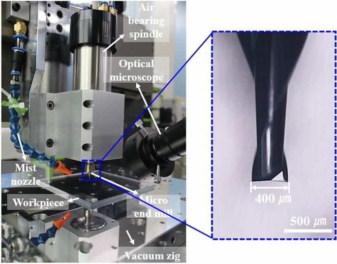
Unlike conventional machining, which commonly works with relatively large cutting tools and features, micromachining may use tools with diameters well below 1 mm. In precision micro-milling research, cutting-edge diameters can range from approximately 1 μm to 1,000 μm, although the exact definition varies depending on the process and application.
The term micromachining is often used interchangeably with micro machining. Both describe manufacturing processes designed to create miniature geometries with controlled dimensions, surface quality, and positional accuracy.
Typical micro-scale features include:
- Micro holes and slots
- Narrow grooves and channels
- Micro gears and shafts
- Thin walls
- Microfluidic channels
- Fine surface textures
- Small cavities and molds
- High-aspect-ratio structures
The key point is that micro machining is not simply “making a small part.” The machining system itself must be capable of controlling tool motion, cutting forces, vibration, heat, and tool wear at a much smaller scale.
How Micro Machining Works
So, how does micro machining work?
The answer depends on the selected process. Material can be removed mechanically, thermally, chemically, or electrochemically.
Mechanical Material Removal
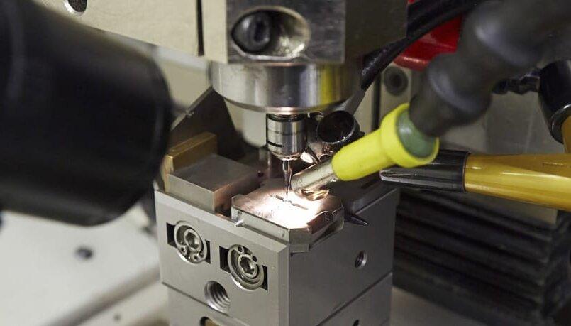
Processes such as micro-milling, micro-turning, and micro-drilling use miniature cutting tools to physically remove material.
A CNC system controls:
- Tool position
- Feed rate
- Spindle speed
- Cutting depth
- Tool path
- Workpiece orientation
Micro-milling is particularly useful for complex three-dimensional features because it can create microchannels, cavities, pockets, textures, and contoured surfaces. Research has shown its usefulness across biomedical, electronics, aerospace, automotive, and mold applications.
Thermal Material Removal
Micro-EDM and laser micromachining remove material through concentrated energy.
Micro-EDM generates controlled electrical discharges between an electrode and a conductive workpiece. Because there is no conventional cutting edge, the process is useful for hard conductive materials and intricate features.
Laser micromachining uses a focused laser beam to melt, vaporize, or ablate material. Short-pulse and ultrafast lasers are particularly useful when heat-affected zones need to be minimized.
Chemical and Electrochemical Removal
Chemical etching selectively dissolves material using chemical reactions, while electrochemical machining removes conductive material through anodic dissolution.
These processes are useful when mechanical cutting would introduce excessive forces, tool wear, or surface damage.
The Four Technical Foundations
Successful micro machining relies on more than a CNC machine. Four factors are especially important:
High-precision machine tools
Rigid structures, thermal stability, low vibration, and accurate motion control are essential.
Micro tooling and energy sources
Small-diameter carbide tools, fine electrodes, and focused laser beams must operate consistently.
CAD/CAM software
Tool paths must account for small geometries, tool diameter, corner radii, workpiece orientation, and cutting conditions.
Measurement and feedback
High-resolution measurement helps detect dimensional errors, tool wear, thermal drift, and positioning deviations.
Modern micro-machining systems increasingly incorporate temperature control, high-resolution feedback, and process monitoring to maintain repeatability.
Micro Machining vs. Conventional Machining
The difference is not simply the size of the finished component. The entire manufacturing process behaves differently at the microscale.
| Factor | Conventional Machining | Micro Machining |
| Feature size | Typically millimeter-scale or larger | Often micrometer-scale |
| Tool size | Relatively large | Often sub-millimeter |
| Cutting force | Easier to manage | Very sensitive to tool engagement |
| Tool deflection | Usually manageable | Can significantly affect accuracy |
| Runout | Important | Extremely critical |
| Vibration | Important | Can directly affect surface quality |
| Thermal effects | Usually manageable | Can cause significant dimensional drift |
| Tool wear | Gradual | Can quickly change feature geometry |
| Measurement | Standard gauges/CMM | Often requires high-resolution inspection |
The Size Effect
One of the most important differences is the size effect.
At the microscale, the undeformed chip thickness can approach the material’s grain size or cutting-edge radius. Instead of behaving exactly like conventional cutting, the material may experience elastic-plastic deformation, ploughing, and changes in chip formation.
As a result, simply scaling down conventional cutting parameters does not necessarily produce good micromachining results. Tool geometry, edge radius, grain structure, runout, and cutting conditions all become much more influential.
Tool Runout Becomes Critical
With a large cutter, a few micrometers of radial runout may have limited influence.
With a 0.2 mm micro end mill, the same runout can represent a significant percentage of the tool diameter.
This can cause:
- Uneven tooth loading
- Premature tool breakage
- Dimensional errors
- Poor surface finish
- Inconsistent tool wear
That is why spindle quality, tool holding, balancing, and tool measurement are fundamental to micromachining.
Major Methods of Micromachining
No single micro machining technology is suitable for every application. The correct process depends on the material, geometry, tolerance, surface finish, production volume, and feature size.
Mechanical Micromachining
Micro Milling
Micro milling uses miniature end mills to produce three-dimensional features.
Typical applications include:
- Micro molds
- Microfluidic channels
- Precision cavities
- Micro grooves
- Optical components
- Small mechanical parts
Its major advantage is geometric flexibility. Unlike some lithography-based processes, micro-milling can directly produce complex 3D structures.
Micro Turning
Micro turning is designed for miniature rotational components such as:
- Micro shafts
- Pins
- Bushings
- Needles
- Small cylindrical components
It is particularly suitable when dimensional accuracy and concentricity are important.
Micro Drilling
Micro drilling produces small-diameter holes in metals, plastics, and other materials.
Applications include:
- Microfluidic holes
- Medical components
- Fuel injector features
- Precision nozzles
- Electronic components
Because chip evacuation becomes increasingly difficult as hole diameter decreases, drilling parameters and coolant delivery must be carefully controlled.
Micro Grinding and Ultrasonic Machining
Micro grinding is useful for hard materials where conventional cutting is difficult.
Ultrasonic machining uses high-frequency vibration to assist material removal and is particularly useful for hard, brittle materials such as ceramics and glass.
Thermal Micromachining
Micro-EDM
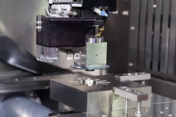
Micro-EDM uses electrical discharges to erode conductive materials.
It offers several advantages:
- Virtually no conventional cutting force
- Suitable for hardened metals
- Excellent for small holes and cavities
- Capable of complex geometries
- No mechanical cutting tool required
It is particularly useful for materials that are too hard or difficult to machine with miniature cutting tools.
Laser Micromachining
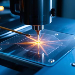
Laser micromachining concentrates optical energy into a very small area.
Depending on the laser type and process parameters, it can be used for:
- Micro drilling
- Cutting
- Surface texturing
- Marking
- Thin-film processing
- Micro patterning
Ultrafast lasers can reduce thermal damage and are increasingly used for precision processing of sensitive materials.
Micro-Electron Beam Machining
Electron beam machining uses a focused high-energy electron beam to remove or modify material.
It can produce extremely fine features but generally requires specialized equipment and controlled processing environments, making it more suitable for specialized applications than general-purpose production.
Chemical and Electrochemical Micromachining
Chemical Etching
Chemical etching selectively removes material through chemical reactions.
It is widely associated with semiconductor and microfabrication processes where large numbers of small structures need to be produced simultaneously.
Electrochemical Micromachining
Electrochemical micromachining removes conductive material through controlled anodic dissolution.
Because there is no physical cutting edge, the process avoids many conventional tool-wear problems and can produce burr-free features with minimal mechanical stress.
Hybrid Micromachining
Some difficult applications benefit from combining multiple processes.
Examples include:
- Ultrasonic-assisted micro milling
- Laser-assisted machining
- Laser-assisted micro cutting
- EDM-assisted processes
Hybrid methods can reduce cutting forces, improve tool life, or make difficult materials easier to process.
Materials Suitable for Micro Machining
Micro machining can be applied to a broad range of engineering materials, but each material requires different process parameters.
Metals and Alloys
Common choices include:
- Stainless steel
- Aluminum
- Copper
- Titanium alloys
- Tool steel
- Carbide
- Nickel alloys
- Nitinol
Titanium and Nitinol, for example, can be challenging because of their mechanical properties and tendency to generate heat during cutting.
Hard and Brittle Materials
These include:
- Technical ceramics
- Glass
- Quartz
- Sapphire
Mechanical cutting may create cracking or chipping, so ultrasonic machining, grinding, laser processing, or other specialized methods may be more appropriate.
Engineering Plastics
Common materials include:
- PEEK
- PMMA
- Polyimide
- PC
- POM
- PTFE
For plastics, thermal control is particularly important because excessive heat can cause melting, deformation, or dimensional instability.
Semiconductor and Composite Materials
Silicon, carbon-fiber composites, and other advanced materials can also require micromachining.
The correct method depends heavily on whether the material is electrically conductive, brittle, heat-sensitive, anisotropic, or abrasive.
Applications of Micro Machining
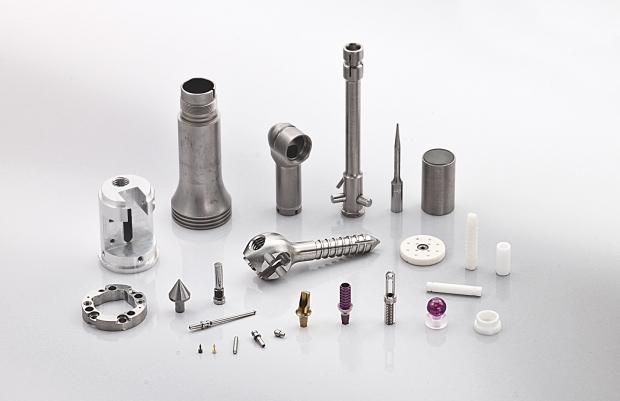
Medical Devices
Medical manufacturing is one of the strongest applications for micromachining because many components must be small while maintaining precise interfaces.
Applications include:
- Surgical instruments
- Micro needles
- Implant components
- Stent-related tooling
- Dental components
- Microfluidic devices
- Lab-on-a-chip systems
Micro-milling is particularly relevant to biomedical manufacturing because it can create complex microstructures and high-aspect-ratio features.
For medical CNC components, manufacturers also need to consider material traceability, inspection, surface condition, and regulatory documentation—not just dimensional accuracy.
Electronics and Semiconductors
Electronic products contain increasingly small components and interfaces.
Micromachining can support:
- Connector components
- Probe components
- Semiconductor tooling
- Micro holes
- Precision fixtures
- MEMS-related structures
- Microfluidic and sensor components
Aerospace
Aerospace applications often combine complex geometry with demanding material and inspection requirements.
Potential applications include:
- Cooling holes
- Micro nozzles
- Precision sensor components
- Miniature mechanisms
- Turbine-related components
- Instrumentation parts
Automotive
Automotive applications include:
- Fuel injector components
- Precision valves
- Sensors
- Micro holes
- Small transmission components
- Injection mold inserts
Precision Optics
Micro machining can also produce molds and tooling for optical components.
Typical applications include:
- Micro lens molds
- Optical textures
- Precision cavities
- Light-guiding structures
Advantages, Challenges, and Solutions
Advantages of Micro Machining
Extremely Small Features
Micro machining can create features that are difficult or impossible to produce economically using conventional tooling.
Complex Geometries
Multi-axis micro milling can produce three-dimensional structures, deep cavities, grooves, and intricate surfaces.
High Precision
With appropriate equipment, tooling, temperature control, and inspection, micromachining can achieve very tight dimensional and positional requirements.
Difficult Materials
Processes such as EDM, laser machining, and ultrasonic machining extend manufacturing options for hardened or brittle materials.
Challenges in Micro Machining
Tool Breakage
A tiny cutter has limited mechanical strength. Excessive feed rate, runout, vibration, or cutting depth can cause catastrophic failure.
Solution: optimize tool diameter, tool geometry, spindle speed, feed rate, radial engagement, and cutting depth. Online tool monitoring can further improve reliability.
Chip Evacuation
Small chips can accumulate in narrow pockets and holes.
Solution: use appropriate coolant or air flow, chip-breaking strategies, peck drilling cycles, and tool-path optimization.
Micro-Burrs
Even a very small burr can interfere with assembly or fluid flow.
Solution: control cutting parameters and incorporate suitable deburring, brushing, polishing, or secondary finishing.
Thermal Drift
At the microscale, small temperature changes can become measurable dimensional errors.
Solution: use temperature-controlled equipment, stabilize the workpiece and machine before production, and monitor critical dimensions.
Tool Wear
A few micrometers of tool wear can change a critical feature significantly.
Solution: establish tool-life limits and inspect tools or critical features during production rather than relying only on final inspection.
How to Select the Right Micro Machining Process
The best process starts with the feature, not the machine.
For Complex 3D Geometry
Choose micro milling when the component requires:
- Pockets
- Curved surfaces
- Slots
- 3D contours
- Complex cavities
For Hardened Conductive Materials
Choose micro-EDM when mechanical cutting is difficult and the workpiece is electrically conductive.
For Small Holes and Fine Patterns
Consider laser machining or micro-EDM, depending on material, hole geometry, depth, taper, and surface requirements.
For Brittle Materials
Glass and ceramics may be better suited to ultrasonic machining, grinding, or laser-based processes than conventional micro cutting.
For Prototype and Low-Volume Production
CNC micromachining is often attractive because it does not require dedicated mass-production tooling. It also allows design changes without rebuilding a complete mold or die.
For High-Volume Production
The calculation changes. Tooling investment, cycle time, automation, process stability, and per-part cost become more important. In some cases, chemical, laser, molding, or other batch-processing methods may outperform CNC micromachining.
When to Use CNC Micro Machining for Your Project
If your component combines small features, complex geometry, tight tolerances, and relatively low production volumes, CNC machining can be a practical starting point.
For example, Kemal provides CNC milling and turning for custom metal and plastic parts, with 3-, 4-, and 5-axis capabilities, prototype-to-production support, and inspection options such as CMM and dimensional reports. Its published CNC capabilities include critical-feature tolerances down to approximately ±0.01 mm depending on geometry and engineering review.
Explore Kemal CNC Machining Services
If you are developing a micro component, precision prototype, miniature mold insert, medical component, or other small CNC part, the most efficient next step is to send the CAD file and drawing rather than trying to select a machining process from the feature size alone.
Kemal can review the geometry, material, critical dimensions, tolerances, and production quantity, then provide manufacturability feedback and a quotation. For prototype projects, Kemal specifically supports CNC milling and turning, DFM feedback, optional CMM/FAI inspection, and finishing.
Have a micro-machined part to manufacture? Upload your CAD drawing, specify the material, critical tolerances, surface-finish requirements, and quantity, and request a quote from Kemal. This allows the engineering team to determine whether CNC milling, turning, EDM, or another process is the better fit for your geometry.
Micro Machining Design Considerations
Good micromachining begins before the part reaches the machine.
Avoid Unnecessarily Small Features
Do not specify a 0.1 mm feature if a 0.3 mm feature performs the same function. Smaller features generally increase tooling cost, machining time, and risk.
Define Critical Dimensions
Not every dimension needs the same tolerance.
Identify:
- Critical hole diameters
- Mating surfaces
- Functional gaps
- Position tolerances
- Flatness requirements
- Surface-finish requirements
This allows the manufacturer to focus precision where it actually matters.
Consider Tool Access
Deep, narrow pockets can require extremely long tools. Long tools are more susceptible to deflection and vibration.
Whenever possible, increase tool access and reduce unnecessary depth-to-width ratios.
Design for Inspection
A feature is not truly manufacturable if it cannot be reliably measured.
Consider how critical dimensions will be inspected during the design stage. CMMs, optical measurement, microscopes, gauges, and specialized measurement systems may all be appropriate depending on feature size.
Micro Machining vs. Other Manufacturing Processes
| Factor | Conventional Machining | Micro Machining |
| Feature size | Typically millimeter-scale or larger | Often micrometer-scale |
| Tool size | Relatively large | Often sub-millimeter |
| Cutting force | Easier to manage | Very sensitive to tool engagement |
| Tool deflection | Usually manageable | Can significantly affect accuracy |
| Runout | Important | Extremely critical |
| Vibration | Important | Can directly affect surface quality |
| Thermal effects | Usually manageable | Can cause significant dimensional drift |
| Tool wear | Gradual | Can quickly change feature geometry |
| Measurement | Standard gauges/CMM | Often requires high-resolution inspection |
The most effective production strategy may also combine several technologies rather than relying on one process.
Future Trends in Micro Machining
AI-Based Process Monitoring
Sensors and machine-learning algorithms can monitor spindle behavior, cutting forces, vibration, temperature, and tool wear.
The goal is to detect process instability before it produces defective parts.
More Hybrid Processes
Hybrid systems combining mechanical cutting with laser, ultrasonic, EDM, or other energy sources are likely to become increasingly important for difficult materials and complex microstructures. Research already highlights assisted micro-milling approaches designed to address limitations involving chip formation, process stability, and difficult-to-machine materials.
Better Thermal Control
As tolerances become tighter, thermal stability becomes as important as nominal machine resolution. Modern precision machines increasingly use temperature control and high-resolution feedback to reduce thermal distortion.
More Sustainable Micromanufacturing
Future processes will increasingly focus on:
- Lower coolant consumption
- More efficient energy use
- Longer tool life
- Reduced material waste
- Automated process optimization
Conclusion
Micro machining goes beyond simply scaling down conventional machining. Factors such as tool geometry, vibration, thermal stability, material behavior, and measurement accuracy become critical at the microscale.
The right process—whether micro milling, micro-EDM, laser machining, or other advanced methods—depends on the part’s geometry, material, feature size, tolerance, surface finish, and production volume. For the best results, have your CAD model or drawing reviewed by a qualified manufacturer for DFM and process evaluation before production.