Knurling patterns are regular ridges or grooves created on a part surface to improve grip, transfer torque, retain mating parts, provide identification, or create a controlled visual texture. For CNC-turned knobs, shafts, handles, thumb screws, and sleeves, the main choices are straight, diagonal, and diamond knurls. Straight knurls create axial ridges, diagonal knurls add a single handed direction, and diamond knurls provide a multidirectional texture. Annular and custom patterns are used when retention, clearance, or identification is the primary requirement.
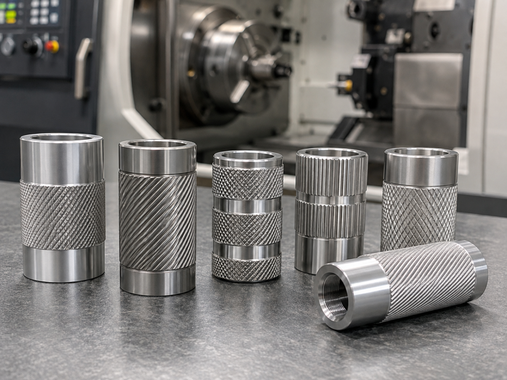
Choosing the pattern name is only the first step. A production-ready knurl specification also needs the pitch or tooth system, direction or angle, process method, finished knurled diameter, length and end condition, material, and acceptance criteria. These variables control how aggressive the texture feels, how the diameter changes, whether the part distorts, and whether the result can be inspected consistently. Without them, two suppliers can produce knurls that look similar but behave differently in the final assembly.
Knurling Patterns at a Glance: Straight, Diagonal, Diamond, and Annular
| Pattern | Surface geometry | Typical function | Main design risk |
| Straight | Ridges run parallel to the part axis | Grip, axial alignment, torque transfer in selected assemblies | Ambiguous ridge direction or insufficient torque validation |
| Left-hand diagonal | Helical ridges slope in one direction | Directional grip, identification, decorative texture | Handedness reversed between drawing and tool |
| Right-hand diagonal | Helical ridges slope in the opposite direction | Directional grip, identification, decorative texture | Same as left-hand diagonal |
| Diamond | Opposing diagonal sets form raised diamonds or intersecting grooves | General hand grip, knobs, handles, thumb screws | Sharp peaks, double tracking, inconsistent tooth fill |
| Annular or circular | Repeated rings run around the circumference | Axial retention, insertion features, selected press-fit applications | High insertion force, shaving, cracking, unclear mating behavior |
| Custom or interrupted | Pattern is limited, indexed, mixed, or locally removed | Branding, orientation, clearance, specialized contact | Higher tooling, indexing, inspection, and repeatability burden |
Terms are not perfectly universal. For example, suppliers may use “annular,” “circular,” or “ring knurl” differently, and a “diamond” description may not define whether the finished surface has raised points or recessed diamonds. A drawing should use a referenced standard or an approved detail rather than relying on the pattern name alone.
Quick selection rule: start with diamond for multidirectional hand grip on knobs and handles; consider straight when axial ridges, selected torque transfer, or a controlled shaft/insert interface is required; use left- or right-hand diagonal when direction, tactile identification, or appearance matters; and use annular or engineered retention features when axial pull-out is the governing requirement. Treat this as a starting point, then confirm pitch, diameter, material, and functional testing.
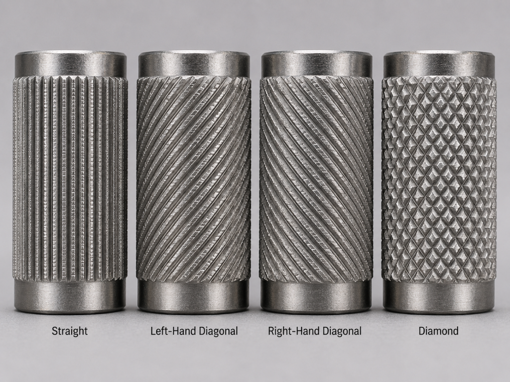
1. Straight Knurling Patterns
A straight knurl normally produces ridges parallel to the axis of a cylindrical part. It creates a texture that resists sliding across the ridges and can transfer torque when paired with a compatible mating component. Common applications include adjustment knobs, tool handles, thumb-operated parts, insert features, and selected shaft-to-component joints.
Straight knurling is not automatically the best option for every press fit. Assembly performance depends on tooth height, mating material, wall thickness, interference, lead-in geometry, insertion direction, and whether the joint must resist rotation, axial pull-out, or both. A pattern that grips a hand well may cut or crack a plastic mating part during insertion.
When the feature is functional, state whether the ridges must be axial, how the mating component is installed, and which performance test governs acceptance.
2. Left-Hand and Right-Hand Diagonal Patterns
A diagonal knurl uses one helical tooth direction. Left-hand and right-hand versions are mirror images. They may be selected for directional grip, product identification, feed behavior, or appearance.
Handedness must be shown clearly. A written callout alone can be misread when teams view a part from different ends. Include a drawing view or pattern symbol with a defined viewing direction. If the direction affects assembly or use, inspect it as a functional characteristic rather than a visual preference.
Single-direction diagonal knurls can create axial force during processing. Toolholder alignment, support, feed direction, part stiffness, and overhang therefore matter. Long, slender workpieces may need additional support and process trials.
3. Diamond Knurling Patterns
Diamond knurling combines two opposing diagonal directions. The intersection creates a crosshatched surface with diamond-shaped peaks or recesses, depending on the tool and requested profile. It is the familiar texture on many knobs, handles, thumb screws, flashlights, and hand-adjusted components.
Diamond patterns are popular because they provide multidirectional grip. However, “medium diamond knurl” is not a controlled production specification. The description omits pitch, tooth angle, final diameter, tooth condition, and process method. Two medium-pattern tools from different systems may not create interchangeable results.
For parts touched by users, review peak sharpness and edge condition. A fully formed coarse diamond can be uncomfortable or damage gloves, while an underfilled pattern may not provide the intended grip. The required aggressiveness should be tied to the operating environment rather than judged only from an enlarged rendering.
4. Annular, Circular, and Retention Patterns
Annular patterns create circumferential rings. They may increase axial retention in molded-over components or mating assemblies, but terminology and tool systems vary. Some suppliers distinguish annular knurling from serration or barbed retention features.
When axial retention is the real objective, specify the requirement in functional terms:
- Mating material and material condition
- Hole or molded feature dimensions
- Insertion direction and maximum assembly force
- Minimum pull-out resistance
- Permitted damage, shaving, or debris
- Temperature, aging, chemical, and cycle conditions
- Whether disassembly is required
A retention feature should be validated in the actual mating material. Tooth geometry that works in a ductile polymer may crack a brittle grade or excessively deform a thin wall.
Male, Female, Raised, and Recessed Knurls
“Male” and “female” are often used to describe the finished tooth form. A male knurl has raised points or crests; a female knurl has recessed points or grooves. The terms can be confused with the tool-wheel profile, which is selected to generate the opposite or complementary surface.
To prevent a tooling interpretation error, show the required finished-part profile in a section or detail view. State whether dimensions apply before or after knurling and whether the measured limit is over the crests, at a reference diameter, or at an adjacent unknurled land.
Cut Knurling vs. Form Knurling
The same pattern may be produced by different methods. Process selection affects forces, chips, diameter growth, material flow, surface condition, and tool access.
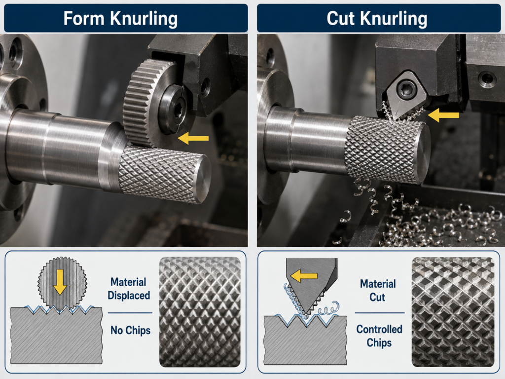
| Factor | Form knurling | Cut knurling |
| Material removal | Primarily displaces material | Removes material with a cutting action |
| Radial load | Generally higher | Often lower when correctly applied |
| Diameter behavior | Material displacement can increase outside diameter | Diameter change follows cut geometry and setup |
| Chips | Normally no conventional cutting chips, though debris can occur | Produces chips that require control |
| Best fit | Ductile materials, rigid setups, suitable geometry | Thin walls, lower-force needs, harder or less formable materials when tooling permits |
| Setup sensitivity | Center height, pressure, tracking, blank diameter | Tool orientation, lead angle, cutting edge, feed, chip evacuation |
| Main failure modes | Double tracking, flaking, excessive force, distorted thin walls | Poor cutting, tool marks, chip damage, incomplete pattern |
This comparison is directional, not absolute. Tool design, material, machine rigidity, part diameter, wall thickness, knurl width, and support can change the result. The manufacturer should select and qualify the method against the finished-part requirement.
For other turned features and tool categories, see Kemal’s guide to lathe cutting tools.
How to Choose Straight, Diagonal, or Diamond Knurling Patterns
1. Start with the Function
Ask what the texture must do:
- Improve wet, dry, or gloved hand grip
- Transfer torque to a mating component
- Resist axial pull-out
- Provide a visual or tactile identifier
- Hide minor handling marks
- Support overmolding or mechanical retention
- Meet a legacy drawing or replacement-part requirement
Once the function is clear, the pattern can be evaluated by measurable performance. If the only requirement is “looks like the old part,” supply an approved sample and define which visual differences are acceptable.
2. Match Knurl Pitch to Part Diameter and Use
Pitch is the spacing between corresponding tooth features. Some inch-based tooling is designated by teeth per inch or diametral pitch, while metric systems commonly use pitch. These systems are related to different tool conventions and should not be converted casually.
A fine pattern creates more, smaller teeth around a given diameter, while a coarse pattern creates fewer, larger teeth and usually feels more aggressive. The appropriate pitch depends on the part diameter, available contact area, material, tooth depth, required grip, appearance target, and whether the knurl is cut or formed. Smaller diameters and cosmetic controls often benefit from a visually proportionate tooth count, while high-grip features may justify a more pronounced texture; neither choice should be made from appearance alone.
Do not copy a pitch from a photograph. Request a physical sample or dimensioned profile when the feel or mating function matters.
3. Balance Grip, Appearance, and Peak Sharpness
For hand-operated knobs and handles, the pattern should be judged at real scale and in the actual use condition. Diamond knurls generally provide multidirectional grip, while straight and diagonal patterns can feel less aggressive or provide a directional tactile cue depending on pitch and tooth form. Wet hands, gloves, contamination, repeated use, and cleaning requirements can change which texture performs best.
Appearance is a separate acceptance requirement. Define whether tooth peaks should be sharp or softened, whether a full pattern is required to the boundary, and whether an approved physical sample controls the visual standard. A rendered image is not enough when gloss, crest shape, or tactile feel is critical.
4. Consider Material and Wall Thickness
Material ductility and hardness affect tooth formation. Aluminum, brass, carbon steel, stainless steel, titanium, and engineering plastics do not respond identically. Work hardening, tearing, flaking, built-up material, and distortion require different process strategies.
Thin-walled tubes and sleeves are especially sensitive to radial force. Review wall thickness, unsupported length, bore tolerance, concentricity, and whether an internal support or cut-knurling method is needed. If the bore is critical, measure it after knurling rather than assuming it remains unchanged.
5. Review Adjacent Features, Knurl Length, and End Conditions
Knurls need approach, tool clearance, and a controlled end condition. Threads, shoulders, grooves, seals, bearing seats, cosmetic lands, and thin edges can limit tool access. The drawing should state whether the knurl may fade out, must stop in a relief groove, or requires a full pattern to a shoulder.
The end transition may need deburring, but excessive edge finishing can flatten the first row of teeth or change the visual boundary.
How to Specify Knurling on an Engineering Drawing
A robust engineering drawing should define enough information for CNC process planning, quotation, tooling selection, and inspection. For a functional knurl, avoid relying on labels such as “fine diamond” or “medium straight.” Include the following where relevant:
- Finished pattern: straight, left-hand diagonal, right-hand diagonal, diamond, annular, or a controlled custom detail.
- Referenced system or standard: identify the standard and edition, or provide the exact supplier-approved tooth profile.
- Pitch designation: metric pitch, teeth per inch, diametral pitch, or another explicitly named system.
- Tooth direction and angle: show the viewing direction when handedness matters.
- Process constraint: specify cut or form only when function or design requires it; otherwise allow the manufacturer to propose the qualified method.
- Blank diameter: define it when it controls tooth formation or a mating feature.
- Finished diameter: give limits and state that they apply after knurling.
- Knurled length and location: define start, stop, relief, runout, and permitted fade.
- Edge condition: state chamfer, radius, burr, and sharpness requirements.
- Functional acceptance: grip, torque, insertion force, pull-out force, master fit, or approved sample.
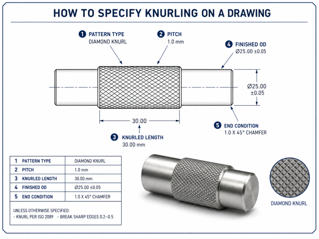
Example callout structure
DIAMOND KNURL; [STANDARD OR CONTROLLED PROFILE]; [PITCH SYSTEM AND VALUE]; [ANGLE IF REQUIRED]; FINISHED OD [LIMITS]; LENGTH [LIMITS]; [CUT OR FORM IF MANDATORY]; END CONDITION PER DETAIL; FUNCTIONAL TEST [METHOD/REQUIREMENT].
This is a structure, not a universal callout. Replace every bracketed field with the project requirement. Standards such as DIN 82 and ASME B94.6 use their own definitions and designation systems; identify the required standard rather than mixing fields from different systems.
Blank Diameter, Tracking, and Final Diameter
Form knurling displaces material. The crest diameter can therefore be larger than the prepared blank diameter. The amount is not a universal percentage because it depends on pitch, tooth depth, profile, material flow, penetration, and process setup.
Good tracking occurs when the tool teeth repeatedly enter the same pattern. Poor compatibility between circumference and tooth spacing can produce double tracking: two overlapping tooth sets instead of one clean pattern. Tool geometry, blank diameter, infeed, holder alignment, and machine rigidity all contribute.
For critical designs:
- Define the required finished diameter, not only the pre-knurl blank.
- Let the manufacturer calculate and qualify the starting diameter for the selected tool system.
- Use a first-article trial when changing tool, machine, material lot, or process method.
- Inspect crest diameter and functional fit after the complete operation.
- Separate the knurled diameter requirement from adjacent bearing, sealing, or thread diameters.
Avoid applying a standard smooth-surface tolerance to a discontinuous tooth crest without defining the measurement method. Different anvils, contact forces, and tooth positions can produce different readings.
CNC Knurling Process Planning
A stable knurl starts before the wheel contacts the part.
1. Review the model, drawing, and assembly
Confirm the functional direction, finished diameter, length, material, mating component, and inspection method. Resolve whether the feature is cosmetic, tactile, or load bearing.
2. Select the wheel and holder
The wheel must match the pattern, pitch, tooth profile, diameter range, material, and cut/form method. The holder must provide suitable alignment and rigidity. A straddle or multi-wheel holder may balance force better than a single-wheel arrangement in some setups.
3. Prepare the blank and edges
Turn the blank to the qualified diameter and surface condition. Add the specified lead-in, chamfer, or relief. Poor blank runout or an unstable surface can carry into the knurl.
4. Control alignment, engagement, speed, and feed
Set center height and tool orientation correctly. Engage the pattern decisively enough to establish tracking without damaging the part. Speed, feed, pressure, dwell, coolant or lubricant, and number of passes must suit the tool supplier’s guidance and actual material.
5. Clean, deburr, and inspect
Remove chips or displaced fragments without rounding functional teeth. Inspect the pattern before releasing the setup for production. Record the approved tool, offsets, blank size, machine, and inspection result.
When knurling is only one feature on a turned part, review the complete route through Kemal’s CNC machining services. Threads, grooves, cross-holes, bearing or sealing diameters, and tight concentric features can affect the holder, tool access, workholding, operation order, and inspection plan.
Common Knurling Defects and Corrective Actions
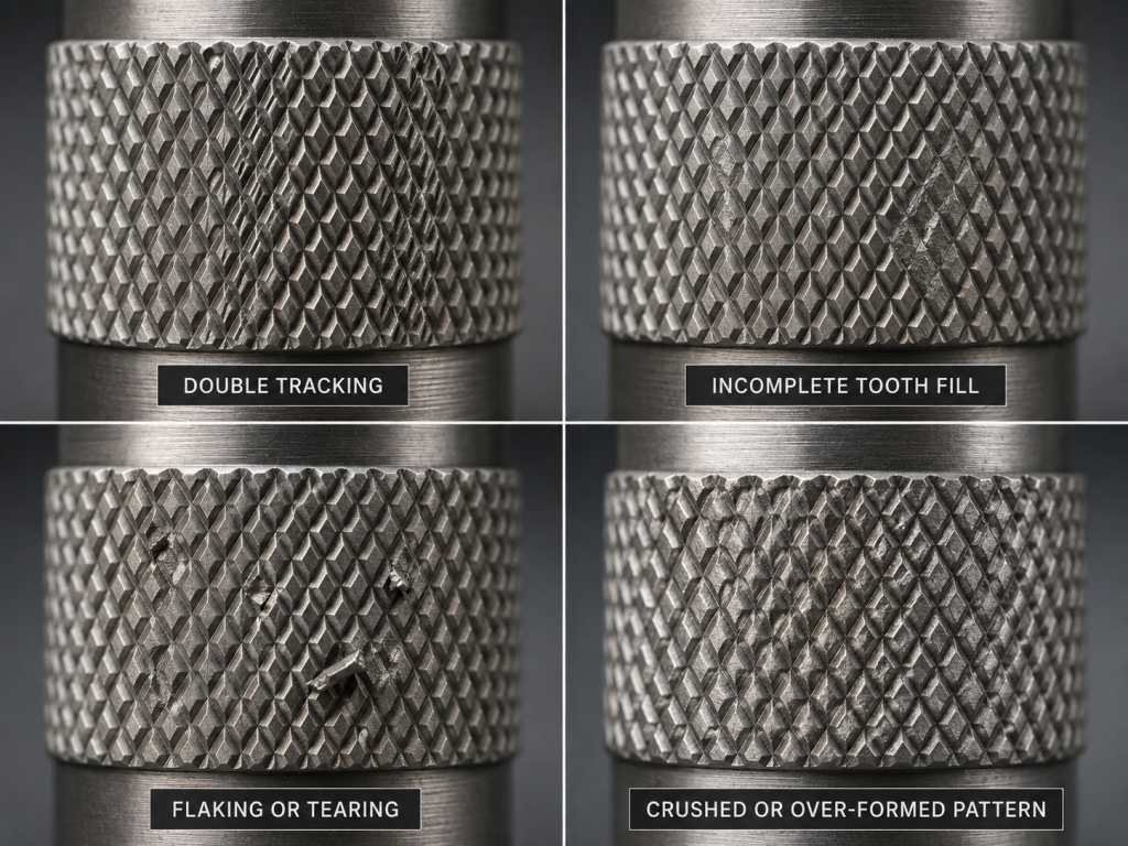
| Defect | What it looks like | Likely causes to investigate | Practical correction path |
| Double tracking | Overlapping or split tooth pattern | Blank diameter mismatch, weak initial engagement, misalignment, runout | Recalculate blank, verify wheel, align holder, establish tracking on a trial part |
| Incomplete tooth fill | Rounded or shallow crests | Insufficient penetration, wrong blank, flex, worn tool | Check setup rigidity, penetration, wheel condition, support, and method |
| Flaking or tearing | Broken crests or surface fragments | Unsuitable forming behavior, excessive pressure, poor lubrication, material condition | Review material, method, wheel geometry, lubrication, and penetration |
| Crushed or over-formed pattern | Flattened, folded, or excessively sharp teeth | Excessive infeed or dwell, repeated uncontrolled passes | Reduce penetration, control passes, verify final diameter |
| Tapered depth | Pattern changes across its width | Tool not square, part deflection, holder movement | Correct alignment and support; reduce overhang |
| Chatter or waviness | Periodic variation beneath the tooth pattern | Low rigidity, spindle/tool vibration, unstable support | Improve workholding, holder rigidity, support, and cutting conditions |
| Burrs at the ends | Raised material near boundaries | Uncontrolled runout, unsuitable chamfer or relief, tool exit | Add an appropriate relief or edge detail and controlled deburring |
| Bore distortion | Bore size or roundness changes | High radial forming load on a thin wall | Add support, change holder/method, revise geometry, inspect after knurling |
| Wrong handedness | Pattern slopes opposite to requirement | Ambiguous view or incorrect wheel arrangement | Add viewing direction and first-article visual standard |
| Variable appearance | Gloss, depth, or peak shape changes | Tool wear, material variation, inconsistent cleaning or setup | Control tool life, material lot, parameters, and visual standard |
Replacing a wheel is not the automatic answer. Diagnose the part, holder, blank, machine, material, and method as one system.
Inspecting a Knurled Feature
Knurled surfaces are discontinuous, so inspection must match the requirement. A surface roughness value such as Ra generally describes a measured profile under defined filtering and sampling conditions; it does not by itself specify knurl pitch, tooth height, crest sharpness, or grip. See the surface roughness guide for the distinction between texture parameters and functional geometry.
An inspection plan may include:
- Pattern type and handedness by visual comparison
- Pitch or tooth spacing using optical measurement or a suitable comparator
- Finished outside diameter with an agreed contact method
- Knurled length, location, runout, and adjacent land dimensions
- Tooth profile or depth on a sectioned qualification sample when required
- Burr, flake, contamination, and peak-condition inspection
- Bore size and roundness after knurling on thin-walled parts
- Functional torque, insertion, pull-out, or master-gauge test
- Approved appearance sample under controlled lighting and magnification
For important projects, align the method, sampling plan, and report format during quotation. Kemal’s quality assurance page describes the broader inspection and documentation path; the actual acceptance criteria must come from the approved project specification.
Pattern Selection by Application
| Application | Starting pattern choice | What must still be verified |
| Hand knob or thumb screw | Diamond or straight | Grip with dry/wet/gloved hand, peak comfort, appearance, corrosion finish |
| Tool handle | Diamond, straight, or custom zones | Hand comfort, cleaning, fatigue use, edge condition |
| Pressed metal insert | Straight, diamond, or retention-specific profile | Hole tolerance, torque, pull-out, insertion force, mating material |
| Overmolded insert | Straight, diamond, annular, or engineered undercut | Resin flow, knit lines, pull-out/torque, temperature cycling, moldability |
| Adjustment ring | Diamond or diagonal | Directional feel, readability, cosmetic boundary, wear |
| Shaft identification | Left/right diagonal or limited knurl | Clear visual distinction, drawing orientation, no interference |
| Decorative sleeve | Diamond, diagonal, or custom | Approved sample, coating behavior, pattern continuity, seam/stop location |
| Knurled shaft or press-fit feature | Straight, diamond, or retention-specific profile | Torque, pull-out, insertion force, mating material, interference, finished diameter, and bore/wall response |
This table is a design starting point. Functional joints require testing with production-intent parts and mating materials.
What to Send for a CNC Knurled-Part Quote
For a manufacturability and quotation review, send enough information to separate appearance requirements from functional requirements:
- 3D CAD model and controlled 2D drawing
- Part number, revision, units, and quantity
- Material grade and condition
- Required knurl pattern and referenced standard/profile
- Pitch system and value
- Finished diameter and knurled length
- Critical dimensional and geometric tolerances, including post-knurl OD or bore limits, runout, and concentricity where applicable
- Cut or form requirement, if mandatory
- Adjacent thread, relief, chamfer, and edge details
- Mating component drawing and material for functional knurls
- Torque, pull-out, insertion, or grip requirement
- Cosmetic zones and approved visual sample
- Coating, plating, passivation, anodizing, or other finish
- Inspection, certificate, traceability, and packaging requirements
Do not send only a rendered image labeled “fine diamond.” A supplier cannot reliably quote tooling, diameter, inspection, and functional risk from that description.
Frequently Asked Questions
What are the most common knurling patterns?
Straight, left-hand diagonal, right-hand diagonal, and diamond are the most common general categories. Annular or circular patterns are used for selected axial-retention functions. Exact names vary by standard and supplier, so the drawing should also define pitch, direction, profile, and finished dimensions.
Which knurling pattern gives the best grip?
Diamond knurling often provides balanced multidirectional hand grip, but there is no universal best pattern. Pitch, tooth depth, peak sharpness, part diameter, gloves, contamination, and contact force affect performance. Test the intended surface in the real use condition.
Does knurling increase part diameter?
Form knurling commonly increases the crest diameter because material is displaced outward. The increase depends on tool geometry, pitch, penetration, material, and process. Define the final knurled diameter and let the manufacturer qualify the starting blank.
Is knurling a cutting or forming process?
It can be either. Form knurling displaces material under pressure, while cut knurling removes material. The suitable method depends on the material, wall thickness, force limit, geometry, machine, and tool system.
How should a diamond knurl be called out on a drawing?
State the finished pattern, referenced standard or controlled profile, pitch system and value, angle if required, finished diameter, length, end condition, process constraint if mandatory, and inspection or functional test. Avoid using only “fine,” “medium,” or “coarse.”
Can knurled surfaces be specified by Ra?
Ra alone does not define a knurl. It does not communicate pattern, pitch, tooth height, crest form, or grip. Use knurl geometry and functional acceptance criteria. Apply roughness requirements only to specifically defined surfaces and measurement conditions.
Why does a knurl create a double pattern?
Double tracking occurs when the tool does not repeatedly follow one tooth path. Blank diameter compatibility, weak initial engagement, tool alignment, runout, holder rigidity, and wheel condition should be checked.
Can a thin-walled part be knurled?
Yes, but radial forming force may distort the wall or bore. The supplier should review support, holder type, cut versus form method, wall thickness, length, material, and required post-knurl bore tolerance.
Conclusions
The best knurling pattern is the one that meets a defined function and can be produced and inspected consistently. For knobs and handles, compare straight, diagonal, and diamond patterns by grip direction, comfort, pitch, and appearance. For shafts, inserts, and retention features, prioritize torque, pull-out, insertion behavior, mating material, and finished diameter. In every case, control the pitch system, material, knurled length, end condition, process method when mandatory, and the acceptance test.
To confirm manufacturability and pricing, view Kemal’s CNC machining capabilities and submit the 2D drawing and 3D CAD model with the knurl callout, material grade, quantity, critical tolerances, required finish, and target functional requirement. The review should confirm the suitable knurling method, finished diameter strategy, adjacent machining sequence, and inspection approach before production.