An injection molding machine converts plastic pellets into repeatable molded parts by coordinating heat, pressure, motion, cooling, and control. The machine is not one mechanism. It is a connected system made up of an injection unit, clamping unit, drive system, electrical controls, safety equipment, and mold interface.
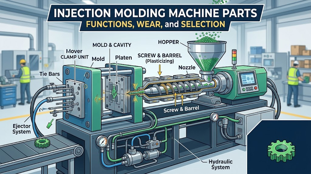
The fastest way to understand injection molding machine parts is to group them by function:
- The injection unit melts, mixes, meters, and injects the plastic.
- The clamping unit closes the mold, resists injection pressure, and ejects the part.
- The drive and control systems create and regulate force, speed, position, and temperature.
- The mold and auxiliary systems shape, cool, and handle the finished part.
This guide explains the main components, what they do, how wear appears in production, and what buyers should verify before ordering a replacement part.
Important distinction: “Injection molding machine parts” usually means components of the molding machine itself, such as screws, barrels, nozzles, platens, tie bars, and hydraulic parts. “Injection-molded parts” means the plastic products made by the process. If your project concerns custom plastic components rather than machine spares, see Kemal’s plastic injection molding services.
Main Injection Molding Machine Parts at a Glance
| System | Main components | Primary function | Typical warning signs |
| Material feed | Hopper, loader, dryer, magnets, feed throat | Deliver clean, conditioned resin | Bridging, contamination, unstable feed |
| Plasticizing and injection | Screw, barrel, check ring, screw tip, nozzle, heater bands | Melt, meter, mix, and inject resin | Shot variation, black specks, slow recovery, leakage |
| Clamping | Fixed and moving platens, tie bars, toggle or hydraulic clamp | Close and hold the mold | Flash, platen movement, uneven clamp force |
| Mold actuation | Ejector, core-pull connections, mold-height system | Release parts and move mold features | Sticking parts, short ejector stroke, timing faults |
| Power transmission | Hydraulic pump, motor, valves, cylinders, servo drive | Produce controlled force and movement | Pressure loss, heat, noise, drift, oil leakage |
| Control and safety | Controller, sensors, thermocouples, relays, guards, interlocks | Coordinate the cycle and protect operators | Temperature error, position error, intermittent stops |
| Thermal management | Cooling channels, heat exchanger, oil cooler, mold temperature controller | Stabilize machine and mold temperature | Long cycle, warpage, oil overheating |
No single warning sign proves that a component has failed. For example, flash can come from insufficient clamp force, mold damage, excessive injection pressure, incorrect material temperature, or an inaccurate mold setup. Troubleshooting should follow the full process chain rather than replacing the first part that appears related.
1. Material-Feeding Components
Hopper
The hopper stores resin above the feed throat. Simple hoppers only hold material; production systems may include a loader, dryer, level sensor, magnet, or material-blending unit.
Moisture-sensitive resins require correct drying before they enter the barrel. A functioning machine cannot compensate for wet material. Splay, bubbles, reduced mechanical properties, and unstable viscosity may be material-conditioning problems rather than failures in the injection unit.
Hopper loader, dryer, and magnet
The loader transfers pellets to the machine, while the dryer controls moisture and temperature. A hopper magnet or screen helps stop metal fragments and foreign material before they damage the screw, barrel, or check valve.
Check filters, hoses, seals, dew point, airflow, and cleaning records. Cross-contamination at the feeding stage can create color streaks, black specks, and inconsistent part properties.
Feed throat
The feed throat connects the hopper to the barrel. It is commonly water-cooled to prevent pellets from softening too early and bridging above the screw. Restricted cooling, an incorrect feed-throat temperature, or accumulated resin can cause irregular feeding.
2. Injection Unit Parts
The injection unit performs three jobs: plasticizing the resin, metering a controlled shot, and pushing that shot into the mold. Small changes in this system can affect fill balance, cushion, part weight, color dispersion, and material degradation.
Reciprocating screw
The screw rotates to convey and melt the resin, then moves forward like a plunger during injection. A general-purpose screw has feed, transition, and metering zones, but geometry varies with the resin and process.
Important screw variables include:
- Diameter and length-to-diameter ratio
- Channel depth and compression ratio
- Flight geometry and mixing features
- Base material, heat treatment, and surface coating
- Clearance between the screw and barrel
Abrasive glass-filled materials and corrosive flame-retardant or chemically aggressive resins can accelerate wear. Screw wear may appear as longer recovery time, unstable melt temperature, loss of shot consistency, or reduced plasticizing capacity. The correct diagnosis normally requires dimensional inspection and process data, not visual judgment alone.
Barrel
The barrel surrounds the screw and contains the melt under heat and pressure. Heater bands raise the barrel to its operating range, while thermocouples provide feedback to the temperature controller.
Barrel wear is often concentrated in high-pressure or high-shear zones. Excessive screw-to-barrel clearance allows material to flow backward, reducing metering efficiency. When evaluating a screw and barrel, inspect them as a matched system rather than replacing one component without measuring the other.
Screw tip, check ring, and non-return valve
The non-return valve at the front of the screw prevents molten plastic from flowing backward during injection. Designs vary, but common assemblies include a screw tip, check ring, and retainer.
A worn or contaminated check valve can cause:
- Inconsistent cushion
- Part-weight variation
- Short shots at otherwise stable settings
- Unstable peak pressure
- Poor repeatability from cycle to cycle
A practical check is to trend cushion, transfer position, peak pressure, and part weight over multiple cycles. A single bad shot is not enough to confirm valve wear.
Nozzle
The nozzle transfers melt from the barrel into the mold sprue bushing or hot-runner interface. Its radius and orifice must match the mold interface. Poor alignment or an incorrect radius can cause leakage, drool, cold slugs, material degradation, or damage around the sprue bushing.
Nozzle selection also depends on resin, shot size, pressure, temperature, and whether the process uses an open nozzle, shut-off nozzle, or another specialized design.
Heater bands and thermocouples
Heater bands create controlled heat zones along the barrel and nozzle. Thermocouples measure temperature for closed-loop control. A loose band, failed heater, misplaced sensor, damaged wire, or poor contact can create temperature overshoot or an apparently normal reading that does not represent the actual melt condition.
When one zone behaves abnormally, verify the heater output, sensor location, wiring, controller signal, and real barrel temperature before changing the molding recipe.
Injection cylinder or electric drive
Hydraulic machines use cylinders and valves to rotate and advance the screw. All-electric machines use servo motors and mechanical transmission systems. Hybrid machines combine elements of both.
The drive type changes the maintenance method, but the production objective is the same: controlled screw speed, injection velocity, pressure, position, and repeatability.
3. Clamping Unit Parts
The clamping unit opens and closes the mold and holds it shut while cavity pressure rises. Its performance affects flash, mold protection, venting behavior, parting-line condition, and tool life.
Fixed and moving platens
The fixed platen supports the stationary mold half; the moving platen carries the moving half. Platen flatness, parallelism, deflection, and the condition of mounting holes influence how evenly force reaches the mold.
An uneven interface can create localized mold stress and parting-line problems. Before blaming the mold, inspect platen condition, mold support, clamp settings, and installation practice.
Tie bars
Tie bars guide the moving platen and carry clamping load in many machine designs. They must remain clean, lubricated as specified, and free from damage. Uneven strain readings or abnormal wear can indicate load imbalance, poor leveling, platen problems, or incorrect mold installation.
Toggle mechanism or hydraulic clamp cylinder
Toggle machines use linked mechanical members to generate high clamp force near the fully closed position. Direct-hydraulic machines use hydraulic cylinders. Each design has different maintenance points, but both require accurate mold-close position, adequate force, and functioning mold protection.
Mold-height adjustment system
The mold-height or mold-thickness adjustment system positions the clamping mechanism for the installed tool. Incorrect setup can prevent full clamping, overload the mechanism, or create false mold-protection conditions.
Ejector system
The machine ejector actuates the mold’s ejector plate after opening. Key variables are position, speed, force, number of strokes, and return confirmation. Ejector problems may actually originate in the mold, including damaged pins, poor lubrication, insufficient draft, undercuts, vacuum, or part shrinkage.
Mold-protection sensors and safety interlocks
Low-pressure mold protection is a control function that helps stop closing motion when resistance is abnormal. Mechanical guards, electrical interlocks, light curtains, and emergency stops protect people and equipment. Safety devices should never be bypassed to maintain production.
4. Hydraulic, Electric, and Control Components
Hydraulic system
A hydraulic system may include the pump, reservoir, filters, valves, manifolds, hoses, seals, pressure sensors, and oil cooler. Contaminated or overheated oil accelerates wear and creates unstable motion.
Useful maintenance data includes oil temperature, filter differential pressure, leakage, pump noise, pressure response, and oil-analysis results. Replacing a valve without correcting contamination can lead to repeat failure.
Servo motors and drives
Electric and hybrid machines use servo motors, drives, encoders, belts, ball screws, or gear systems depending on the design. Alarm history, position feedback, bearing condition, lubrication, and drive temperature help identify faults.
Controller, sensors, and electrical cabinet
The controller coordinates sequence, pressure, speed, position, time, and temperature. Sensors may monitor screw position, platen position, pressure, temperature, guard status, ejector return, and other conditions.
Intermittent faults often come from connectors, cables, grounding, heat, vibration, or contamination rather than the controller itself. Record the alarm code, cycle step, machine condition, and environmental condition before resetting the fault.
5. The Mold Interface Is Part of the System
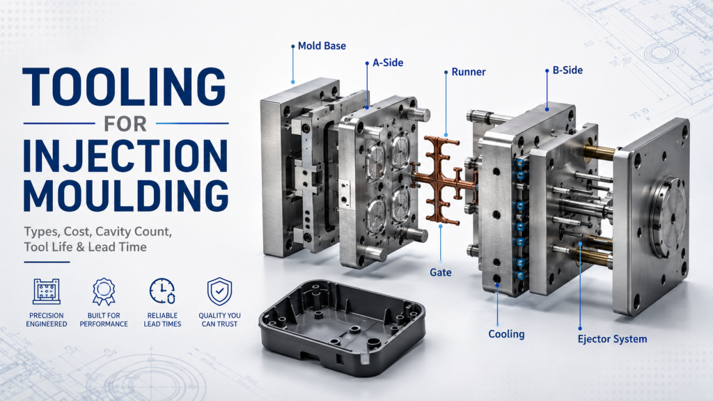
The mold is not normally classified as a permanent part of the injection molding machine, but the machine and mold function as one production system. Their interfaces must match in several areas:
- Platen size, mounting pattern, and mold dimensions
- Tie-bar spacing and machine daylight
- Mold thickness and opening stroke
- Nozzle radius, nozzle reach, and sprue-bushing geometry
- Ejector pattern and available ejector stroke
- Core-pull or unscrewing connections
- Cooling-water, hot-runner, and sensor connections
- Required clamp force, shot capacity, and plasticizing capacity
A machine may have sufficient advertised tonnage yet still be unsuitable because of tie-bar spacing, shot size, platen dimensions, injection rate, or mold opening requirements. Machine selection should therefore be checked against the actual mold and resin, not only the projected part area.
For new tooling, early injection mold design review helps confirm these interfaces before steel is cut. The same interface data should be controlled during injection mold manufacturing.
Common Wear Symptoms and What to Check First
| Production symptom | Possible machine-related causes | Other causes to rule out |
| Shot-weight variation | Worn check ring, screw/barrel wear, unstable feed, pressure control fault | Wet or inconsistent resin, changing regrind ratio, gate variation |
| Short shots | Leakage across check valve, heater failure, insufficient injection response | Blocked gate/vent, low melt or mold temperature, inadequate shot size |
| Flash | Clamp-force problem, platen issue, tie-bar imbalance | Damaged parting line, excessive pressure, low material viscosity |
| Black specks | Dead spots in barrel/nozzle, heater-control fault, degraded residue | Contaminated resin, poor purging, hot-runner degradation |
| Long recovery time | Screw/barrel wear, drive problem, feed restriction | Incorrect back pressure, poor drying/feed, unsuitable screw geometry |
| Nozzle leakage | Worn nozzle tip, poor alignment, damaged seat, shut-off fault | Incorrect nozzle temperature or decompression setting |
| Unstable temperature | Heater, thermocouple, wiring, contactor, controller output | Excessive shear or incorrect process settings |
| Part sticking or poor ejection | Ejector control fault, insufficient machine stroke | Mold damage, insufficient draft, undercut, vacuum, shrinkage |
| Oil overheating | Cooler restriction, pump wear, internal leakage, oil condition | High ambient temperature or excessive process demand |
This table is a diagnostic starting point, not a replacement-parts list. Collect trend data and inspect the complete system before authorizing repairs.
How to Specify Replacement Injection Molding Machine Parts
Ordering by a familiar name such as “screw,” “nozzle,” or “seal” is not enough. Machine revisions, resin requirements, and previous modifications can change the correct specification.
1. Identify the machine precisely
Record the manufacturer, model, serial number, year, control version, screw diameter, and relevant assembly number. Photograph the nameplate and installation area. Do not rely only on a handwritten part label.
2. Capture the component definition
Provide the OEM part number, assembly drawing, material specification, heat treatment, coating, critical dimensions, fits, threads, sealing surfaces, surface finish, and interface geometry where available.
For reverse-engineered components, agree on which dimensions are functional and which are only reference dimensions. Wear on the old part must not automatically become the specification for the new one.
3. State the processing environment
List the resins, fillers, additives, temperature range, pressure, cycle rate, and cleaning method. Glass fiber, mineral filler, flame retardant, PVC, high-temperature polymers, and recycled content can require different material or surface-treatment choices.
4. Define inspection and traceability
The inspection plan should match the failure risk. Depending on the part, it may include dimensional inspection, material certification, hardness, coating thickness, runout, concentricity, straightness, surface roughness, thread gauges, or functional assembly checks.
Kemal’s quality assurance page explains the broader approach used to verify manufactured parts and tooling. Actual acceptance criteria should always come from the approved drawing and purchase specification.
5. Confirm installation and validation
Before installation, compare the replacement with the approved drawing and retained sample. After installation, validate the machine gradually and record relevant values such as recovery time, cushion, part weight, pressure profile, temperature stability, leakage, and alarm history.
Where a custom metal component is appropriate and the drawing is controlled, CNC machining services may support manufacturing and inspection. Safety-critical, pressure-bearing, electrical, proprietary, or certified components should be sourced and approved according to the machine manufacturer’s requirements.
Repair, Reverse Engineer, or Buy an OEM Part?
| Option | Best used when | Main advantage | Main risk |
| OEM replacement | Safety, control, pressure, or proprietary geometry is involved | Known compatibility and documentation | Cost or lead time |
| Qualified aftermarket part | Specification is established and supplier capability is proven | Alternative cost and availability | Material or dimensional mismatch |
| Reverse-engineered custom part | OEM support is unavailable and the functional specification can be verified | Restores obsolete equipment | Copying worn geometry or missing hidden requirements |
| Repair or reconditioning | Damage is limited and a validated repair procedure exists | May reduce downtime and material use | Reduced life or distortion if repair is unsuitable |
The decision should consider downtime, failure consequence, available drawings, certification needs, validation cost, and total service life. The lowest unit price is not necessarily the lowest production risk.
Preventive Maintenance Priorities
A useful maintenance program is based on operating hours, resin severity, machine condition, and process trends rather than a generic calendar alone.
- Keep resin and regrind free from metal and foreign material.
- Verify drying and feed-throat cooling.
- Trend screw recovery time, cushion, shot weight, peak pressure, and temperature.
- Inspect nozzle alignment and leakage.
- Maintain lubrication according to the machine manual.
- Monitor hydraulic oil cleanliness, temperature, filters, and leakage.
- Inspect wiring, connectors, guards, and interlocks.
- Check platen and mold-mounting condition.
- Record component measurements during planned shutdowns.
- Retain failure photos, inspection reports, and replacement history.
Trend data is especially valuable because progressive wear may remain hidden until the process window becomes too narrow. A small but consistent change in recovery time or cushion can be more informative than one sudden defective part.
Buyer Checklist Before Requesting a Quote
Prepare the following information before contacting a supplier:
- Machine manufacturer, model, serial number, and year
- Component name and OEM part or assembly number
- Drawing, 3D file, or dimensioned inspection record
- Photos of the component and installation area
- Material, heat treatment, hardness, coating, and finish requirements
- Resin type, filler content, operating temperature, and service conditions
- Critical dimensions and acceptance method
- Required quantity and delivery date
- Failure symptoms and inspection findings
- Safety, certification, and traceability requirements
If no drawing exists, start with a technical review rather than requesting an immediate production quote. A controlled measurement and approval process is necessary before a worn component can become a reliable manufacturing reference.
Frequently Asked Questions
What are the main parts of an injection molding machine?
The main groups are the material-feeding system, injection unit, clamping unit, hydraulic or electric drive, controller and sensors, safety system, thermal-management system, and the mold interface. Important individual components include the hopper, screw, barrel, check ring, nozzle, platens, tie bars, clamp mechanism, ejector, pumps or servo motors, heater bands, thermocouples, and controller.
Which injection molding machine parts wear fastest?
Wear depends on resin, filler, temperature, pressure, contamination, cycle rate, and maintenance. Screws, barrels, check rings, nozzle components, seals, heater bands, filters, and moving joints are common inspection points. Glass-filled or corrosive materials can accelerate wear, but service life cannot be predicted from material name alone.
How do I know whether the screw or barrel is worn?
Possible signs include longer recovery time, unstable shot size, reduced plasticizing output, inconsistent cushion, and greater difficulty holding a stable process. Confirm the cause by trending process data and measuring both screw and barrel against the applicable specification.
Can a worn machine component cause molding defects?
Yes, but most visible defects have several possible causes. A worn check valve may contribute to short shots or weight variation, while clamp or platen problems may contribute to flash. Material, mold, setup, and process conditions must also be checked.
Can injection molding machine parts be reverse engineered?
Some non-proprietary mechanical components can be measured and manufactured when the functional requirements are known. However, an old part may already be worn or distorted. Safety-critical, pressure-bearing, electrical, certified, or proprietary components require additional controls and may need OEM sourcing.
What is the difference between machine parts and injection-molded parts?
Machine parts are components used to build or maintain the molding machine. Injection-molded parts are the plastic products made inside a mold. Buyers searching for custom housings, covers, brackets, connectors, or other plastic components generally need molding and tooling support, not machine spares.
Final Takeaway
Injection molding machine parts work as an integrated system. The screw and barrel control plasticizing, the check valve supports shot repeatability, the nozzle connects the machine to the mold, the clamping unit resists cavity pressure, and the drive and control systems coordinate every movement. Replacing a part without diagnosing the material, mold, setup, and process can leave the real problem unresolved.
For a new plastic product, Kemal can review the manufacturing path through mold design, mold manufacturing, plastic injection molding, rapid prototyping, and inspection. For a defined custom metal component, provide the approved drawing, material, critical tolerances, service conditions, and inspection requirements for review. Contact Kemal to discuss the appropriate manufacturing route.