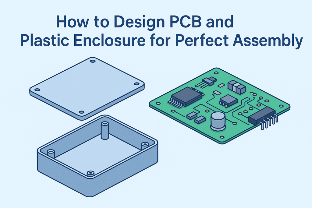
A perfect fit between the PCB and its plastic enclosure is essential for reliable product performance. Poor alignment can cause stress on connectors, heat buildup, or assembly issues — even when the circuit design itself is flawless.
Good assembly design ensures that electronic components stay secure, function properly, and pass durability tests without rework. Understanding how to coordinate PCB layout and enclosure structure from the start saves time, reduces cost, and guarantees a cleaner, more professional final product.
Key Assembly Considerations During PCB Design
A perfect enclosure fit begins with a precise PCB.
Even a fraction of a millimeter off in the board outline, hole position, or connector height can create alignment issues during assembly. That’s why mechanical accuracy must be part of the PCB design process — not an afterthought for the enclosure engineer to fix later.
When designing your board, confirm that:
- The outline shape and hole locations match the mechanical model.
- All keep-out zones align with enclosure walls and components.
- Tolerance stack-ups between the PCB and enclosure remain consistent once fasteners and connectors are installed.
Also, verify board thickness and mounting point height early.
Small variations in these dimensions directly affect how the board seats inside the housing and whether the connectors align correctly with the openings.
Before transitioning to mechanical design, double-check that your PCB dimensions and hole placements meet production tolerances.
Partnering with a precision PCB manufacturer such as ALLPCB ensures dimensional stability and repeatable quality across batches — creating a solid foundation for seamless enclosure integration.

Designing the Enclosure for Reliable Assembly
1. Define the Assembly Method Early
Before starting the enclosure design, determine how the PCB will be fixed inside the housing. Each assembly method, such as screw bosses, snap-fits, or press-fit pillars, has its own structural and manufacturing implications.
- Screw bosses offer strong retention but require careful spacing and support ribs to avoid cracking under torque.
- Snap-fits enable tool-less assembly but need precise flexibility control in the latch arms to prevent fatigue or breakage.
- Press-fit pillars are ideal for compact assemblies but depend on tight dimensional tolerance between the post and PCB hole.
Selecting the wrong method late in the process can force costly mold rework. The enclosure and PCB design teams should align on the fastening strategy during the early concept stage.
2. Ensure Structural Support and Alignment
The enclosure must hold the PCB securely while protecting it from vibration and external loads.
Key structural considerations include:
- Mounting bosses and standoffs positioned under heavy components (like transformers or connectors) to prevent bending.
- Guide slots or rails to position the PCB accurately during assembly, reducing the risk of misalignment.
- Support ribs or partitions to absorb impact and maintain rigidity without adding unnecessary weight.
Even small misalignment between the housing and the board can lead to solder joint stress or connector offset, especially in products exposed to movement or temperature variation.
3. Balance Wall Thickness and Material Flow
Wall thickness directly affects both mechanical performance and moldability.
- Maintain uniform wall thickness (typically 2.0–2.5 mm for ABS or PC/ABS) to prevent warpage or sink marks.
- Add reinforcing ribs instead of thicker walls when extra strength is needed—this reduces cycle time and improves cooling efficiency.
- Use proper draft angles (1°–2°) to ease part ejection without scuffing surfaces.
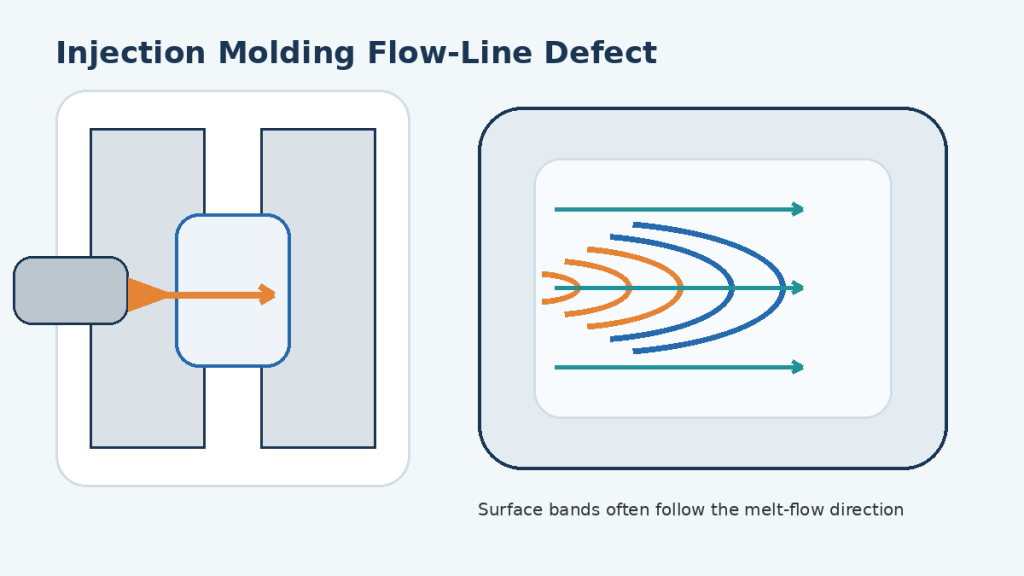
Material flow simulation during the mold design stage can identify air traps, weld lines, or uneven shrinkage zones that may later affect assembly fit.
4. Minimize Stress on the PCB
A good enclosure design distributes loads evenly instead of transferring force directly to the PCB.
Avoid tight interference fits or mounting points that flex the board when fastened. If possible, use floating screw holes or silicone pads under the PCB to absorb vibration.
Thermal expansion differences between plastic and the fiberglass board (FR-4) should also be considered — especially in high-temperature environments where expansion can shift alignment over time.
5. Design for Manufacturability and Maintenance
Enclosure reliability also depends on how easy it is to produce, assemble, and maintain.
- Minimize the number of parts to simplify assembly.
- Avoid deep undercuts unless necessary; if unavoidable, plan for side actions or sliders in the mold.
- Use textured surfaces to hide flow marks and minor imperfections.
- Provide clear access points for screws, ports, and testing.
A design that looks perfect in CAD can fail in production if manufacturing constraints aren’t considered early. Collaboration with an experienced molding partner helps identify potential tooling issues before they turn into costly production delays.

6. Validate with Prototyping and Fit Testing
Before moving to mass production, build functional prototypes—either 3D-printed or soft-tooled—to confirm assembly fit and ergonomics.
Prototyping helps you see how the PCB actually interacts with the enclosure, not just how it looks in CAD.
If your enclosure includes brackets, panels, or EMI/RF shields, consider validating those formed-metal interfaces in parallel with your plastic housing using sheet metal fabrication services.
During fit testing, engineers can:
- Check clearances for connectors, cables, and snap features.
- Verify that mounting holes, bosses, and ports align as designed.
- Assess how the assembly feels during insertion, fastening, or handling.
Iterating at this stage saves far more time and cost than correcting issues after mold fabrication.
A small tweak made in plastic or resin is far cheaper than a tool modification in steel.
By combining digital simulation with hands-on testing, designers can confidently finalize structures that balance manufacturability, durability, and ease of assembly.
In the end, reliable enclosure design isn’t about visual appeal — it’s about mechanical integrity and production readiness.
When you standardize wall thickness, align fasteners carefully, and validate every fit through prototypes, the PCB and housing integrate seamlessly — ensuring consistent, long-term performance under real-world conditions.
Material and Tolerance Design
1. How Materials Behave in the Real World
Designing a PCB enclosure is never just about geometry—it’s about understanding how real materials behave under heat and stress.
Plastics expand, contract, and flex; PCBs barely move. That difference sounds small, but it becomes critical inside compact housings. A few tenths of a millimeter of thermal shift can bend a connector or stress a solder joint.
To handle this, experienced engineers avoid over-constraining the board. They add slotted holes, soft pads, or floating mounts so the PCB can move slightly as the plastic expands. This flexibility prevents cracking and maintains electrical integrity, especially in products that heat up or cool down frequently.
2. Designing with Tolerance in Mind
Injection-molded plastic parts can’t match the precision of machined components, and that’s fine—if you plan for it.
Instead of forcing tight fits everywhere, define which areas truly need precision. For example:
- Connector cutouts and interface zones should maintain tight tolerances.
- Internal walls or standoffs can tolerate more variation.
- Snap-fit features should include small clearances to absorb shrinkage.
By distinguishing between critical and non-critical dimensions early, you let the design adapt to natural variation rather than fail because of it. This is the essence of good mechanical engineering—knowing where perfection matters and where it doesn’t.
3. Choosing the Right Plastic for Dimensional Stability
Not all polymers behave the same once molded. The choice of resin defines how much your part will warp, shrink, or hold shape over time.
- PC/ABS offers a balance of toughness and rigidity—ideal for consumer electronics.
- PBT provides excellent dimensional stability and electrical insulation.
- Glass-filled nylon adds stiffness but absorbs moisture, which can alter fit over time.
Selecting the right material means predicting how the product will live: Will it face high heat? Daily handling? Long-term vibration? Matching these realities to the resin’s behavior keeps assemblies consistent from the first to the last production batch.
4. Engineering Predictability, Not Perfection
Perfect geometry exists only in CAD. Real parts shift as they cool, age, and experience stress. Instead of chasing impossible precision, design for predictable behavior.
Use simulations and prototypes to study shrinkage, expansion, and stress points. Collaborate with mold designers to confirm that tolerances are achievable before cutting steel.
In the end, the goal isn’t to make parts that measure perfectly at room temperature—it’s to make assemblies that still fit perfectly after years of heat cycles, vibration, and wear.
Final Integration: Collaborative Design for Manufacturing
1. Collaboration Begins Before CAD
Perfect assemblies are rarely the result of late-stage fixes—they’re born from early collaboration. When PCB designers, enclosure engineers, and manufacturing partners communicate from the start, problems like connector misalignment or warpage never have the chance to appear.
This means sharing 3D data early, agreeing on tolerance zones, and confirming assembly methods before finalizing designs. A five-minute discussion between electrical and mechanical teams can prevent weeks of mold modification later.
2. Align Design Intent Across Disciplines
Each team sees the same product differently:
- The PCB designer focuses on component layout and heat dissipation.
- The mechanical engineer cares about fit, strength, and assembly sequence.
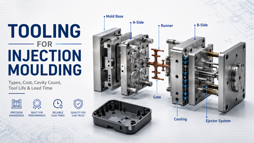
- The mold designer thinks in terms of draft angles, gate placement, and shrinkage flow.
Bridging these perspectives takes active coordination. Using shared CAD environments and Design for Manufacturability (DFM) reviews allows everyone to test assumptions in one digital space. When design intent is aligned, trade-offs become decisions, not arguments.
3. Prototype, Validate, and Iterate Together
No simulation fully replaces a physical test. Prototyping with 3D printing or soft tooling gives teams a chance to validate how parts interact—how the PCB slides in, how connectors click, how the enclosure flexes under load.
Each prototype isn’t a cost; it’s a checkpoint. Testing at this stage reveals clearance issues, assembly friction, or thermal hotspots early—long before mass production makes them expensive to fix.
When mechanical and PCB suppliers collaborate, iteration becomes a process of refinement, not repair.
4. Reliable Partners Make Integration Effortless
Modern manufacturing works best when every contributor specializes. PCB vendors ensure dimensional precision and electrical consistency, while injection molding partners guarantee mechanical strength and surface quality.
Working with a dependable PCB partner provides a stable foundation for precise board fabrication. Combined with an experienced molding manufacturer such as Kemal, your enclosure achieves the perfect fit, finish, and repeatability that mass production demands.
5. From Design to Production: One Continuous Line
The ultimate goal isn’t just making a good PCB or a good enclosure—it’s building a product that fits together seamlessly at every stage, from prototype to assembly line.
That level of reliability only happens when design, testing, and production flow as one continuous process. By fostering open communication and shared accountability, teams turn manufacturing from a hand-off into a partnership.
Conclusion
Designing a perfect fit between a PCB and its plastic enclosure is more than a matter of precision—it’s a mindset that combines electrical design, mechanical reasoning, and manufacturing experience. Every screw boss, mounting hole, and tolerance choice reflects how well these disciplines communicate. When teams collaborate early, choose materials wisely, and validate their work through real prototypes, assembly becomes predictable rather than risky.
The result isn’t just a product that looks good—it’s one that performs flawlessly, batch after batch, because it was designed with both precision and empathy for the realities of production. In modern manufacturing, true quality doesn’t come from individual expertise alone; it comes from the integration of design and process working together as one.