HDPE is one of the most widely used thermoplastics in injection molding—lightweight, impact-resistant, and able to handle harsh chemicals without breaking down. Yet its high shrink rate and crystalline structure mean that small mistakes in processing can quickly lead to warpage, sink marks, or inconsistent dimensions.
In this guide, we’ll focus on the parameters that matter most when molding HDPE, along with practical tips and solutions to common defects. By applying these practices, you can achieve consistent, high-quality HDPE parts.
Understanding HDPE for Injection Molding

High-density polyethylene (HDPE) is a semi-crystalline thermoplastic in the polyolefin family. Its combination of low density, high impact strength, and chemical resistance makes it a popular choice for molded products that need to be lightweight yet durable.
Key Properties:
- Density (0.94–0.97 g/cm³): Lower density means lighter parts, which reduces material cost per piece. But in high-load applications, confirm wall thickness can still support mechanical strength.
- Impact resistance: HDPE holds toughness even at −40°C, making it suitable for cold-chain packaging and outdoor equipment housings without embrittlement.
- Chemical resistance: Withstands acids, bases, and many solvents. Ideal for chemical containers, but note: aromatic hydrocarbons (like benzene) can still cause swelling.
- Electrical insulation: Naturally non-conductive—works for low-voltage housings. If anti-static properties are needed, additives must be specified early, as they can alter flow and shrinkage.
Molding Behavior — How It Affects Your Mold Design
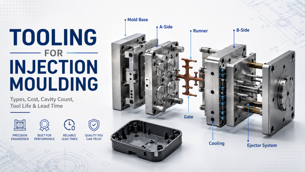
When working with materials like HDPE, thoughtful mold design decisions often determine whether parts meet dimensional accuracy and performance requirements.
Crystalline structure: HDPE’s semi-crystalline nature brings a shrinkage rate of 1.5–3.0%, much higher than amorphous plastics. This means you can’t simply design cavities to nominal part size—tool dimensions must be offset carefully, or your first shots will likely come out undersized. Many designers use actual shrinkage data from trial runs or material suppliers to fine-tune tooling dimensions before steel is cut.
High shrink rate: The same shrinkage also drives warpage when the wall thickness varies. Thin areas cool faster than thick ones, pulling the part out of shape. That’s why experienced mold designers push for uniform wall thickness and balanced cooling channels. These two factors alone often decide whether HDPE parts stay flat or end up twisting after ejection.
Good flow: HDPE flows well enough to fill thin walls under 1.5 mm, but cooling too quickly can freeze the melt before the cavity fills. Gate locations and runner sizes aren’t just geometry choices here—they control melt temperature and flow length, directly affecting whether you get a complete part or one with short shots.
Grades and Where They Work Best
| Grade | Application Examples | Why Choose It |
| General-purpose | Storage bins, crates, industrial parts | Cost-effective, broad usability |
| Impact-modified | Automotive bumpers, playground equipment | Maintains toughness under repeated impact |
| Food-grade | Bottle caps, food containers | Meets FDA/EU standards, safe for direct contact |
When choosing between impact-modified and general-purpose grades, test samples in actual end-use conditions. Lab impact data doesn’t always reflect performance after UV exposure or chemical contact—two factors that often shorten part life in the field.
Comparison with PP and LDPE
| Property | HDPE | PP | LDPE |
| Density (g/cm³) | 0.94–0.97 | 0.90–0.91 | 0.91–0.93 |
| Tensile Strength (MPa) | 20–37 | 25–40 | 8–12 |
| Impact Resistance | High | Medium | Very High |
| Shrinkage (%) | 1.5–3.0 | 1.0–2.5 | 1.5–3.0 |
| Heat Deflection Temp (°C) | ~75–90 | ~95–110 | ~65–80 |
| Chemical Resistance | Excellent | Good–Excellent | Excellent |
| Molding Temp (°C) | 180–230 | 200–250 | 160–210 |
| Typical Applications | Containers, pipe fittings, automotive parts | Automotive interiors, appliance housings | Film, squeeze bottles, cable insulation |
Recommended Processing Parameters for HDPE Injection Molding
Selecting the right processing parameter is critical for HDPE. Because it’s a semi-crystalline material with a relatively high shrink rate, small deviations in temperature, pressure, or cooling can have a big impact on part quality.
| Parameter | Typical Range | Practical Notes & Impact |
| Barrel temperature | 180–230 °C | Below 180 °C, melt flow is poor and can cause short shots; above 230 °C, HDPE can degrade, producing odor and discoloration. Adjust by zone for stable melt flow. |
| Mold temperature | 20–60 °C | Lower mold temps shorten cycle time but can lead to uneven shrinkage; higher temps improve surface finish and dimensional stability. Match to part requirements. |
| Injection pressure | 70–120 MPa | Use higher pressure for thin walls or long flow paths. Excessive pressure may cause flash or internal stress. |
| Injection speed | Medium–High | Faster fill reduces weld lines and voids, but too fast can introduce stress or flashing. Balance with gate design. |
| Cooling time | 10–30 s | Too short increases warpage risk; too long extends cycle time unnecessarily. Base on wall thickness and mold cooling efficiency. |
| Shrinkage | 1.5–3.0 % | Plan mold dimensions to compensate. Higher mold temps and slower cooling reduce shrinkage variation. |
If you’re producing a 3 mm wall-thickness HDPE container:
- Fill + Pack: ~4 s at medium-high speed and ~90 MPa
- Cooling: ~18 s with 25 °C mold temp
- Ejection + Reset: ~3 s
Total cycle time ≈ 25 s per part
By raising mold temperature to 40 °C and improving cooling channel layout, you might cut cooling time by 2 s while improving dimensional stability—saving ~7% cycle time over a full production run.
Processing Tips for Better HDPE Parts
Getting good results with HDPE is about more than just setting the right temperatures and pressures. The way you handle the material, design your tooling, and manage cooling all influence part quality, scrap rates, and cycle time.
1. Material Handling
- Drying: HDPE is not hygroscopic, so drying isn’t usually required. However, moisture on pellet surfaces can still cause splay or bubbles—especially if the material has been stored in humid conditions. Keep resin in sealed containers and avoid long exposure before molding.
- Contamination control: Even small amounts of incompatible polymers can cause streaks or weak spots. Dedicate hoppers and conveying lines to HDPE, or flush thoroughly before changeovers.
2. Screw and Barrel Setup
- Screw design: Use a general-purpose screw or one designed for polyolefins with a compression ratio of 2.0–3.0. This provides enough shear to homogenize the melt without overheating it.
- Back pressure: Keep low to avoid excessive shear heat—just enough to get consistent melt mixing.
3. Gate and Runner Design
- Gate type: Direct gates or pin-point gates work well. Ensure a smooth transition from runner to gate to minimize shear.
- Runner sizing: Avoid undersized runners; HDPE’s good flow means you can use smaller gates than for many engineering plastics, but too small increases shear stress and potential degradation.
4. Molding Strategy
- Mold temperature: Keep consistent across all cavities to avoid differential shrinkage. Uneven cooling is a common cause of warpage.
- Cooling rate: Rapid cooling can trap internal stress. For parts requiring dimensional stability, use slightly higher mold temperatures and balanced cooling circuits.
3 Design Adjustments to Reduce Warpage and Sink Marks
- Uniform wall thickness: Keep variations within ±10% to ensure even cooling and shrinkage.
- Proper rib design: Rib thickness should be ≤60% of adjoining wall thickness to avoid sink marks.
- Balanced gate placement: Feed thicker sections first and ensure symmetrical filling to reduce uneven shrinkage.
Common Issues in HDPE Injection Molding and How to Solve Them
Even with correct parameters, HDPE’s high shrink rate and crystalline structure can make it prone to specific molding defects. The table below lists common issues, the most likely causes, and proven solutions that can be applied in production.
| Defect | Possible Causes | Solutions |
| Warpage | Uneven cooling, large wall thickness variation, unbalanced fill | Maintain uniform wall thickness; balance runner and gate design; improve cooling channel layout; keep mold temperature consistent across cavities |
| Sink marks | Overly thick sections, insufficient packing pressure/time, poor rib design | Increase packing pressure/time; redesign ribs to ≤60% of wall thickness; gate closer to thick sections |
| Flash | Mold misalignment, insufficient clamping force, excessive injection pressure | Inspect and repair parting line; increase clamping force; lower injection pressure while maintaining fill |
| Short shot | Poor melt flow, low injection pressure/speed, small gates/runners | Increase melt temperature and/or injection speed; enlarge gates/runners; ensure adequate venting |
| Burn marks | Trapped air, excessive shear heating, high injection speed | Improve venting at end-of-fill areas; reduce injection speed; check runner and gate design for sharp turns |
| Voids / bubbles | Moisture contamination, low packing pressure, fast cooling | Ensure resin is clean and dry; raise packing pressure; optimize cooling to avoid premature skin formation |
Quick Troubleshooting Flow
- Identify the defect location: Center of part, edges, or near gates?
- Check processing data: Compare actual temperature/pressure profiles against your standard.
- Inspect tooling: Parting line fit, vent depth, cooling channel blockage.
- Adjust one variable at a time: Prevents masking the real cause.
- Document the fix: Create a permanent record for future reference.
Tip: Keeping a defect log with photos and parameter changes can cut troubleshooting time by over 50% in recurring production runs.
Design Considerations for HDPE Parts

Designing for HDPE injection molding is not only about meeting functional requirements—it’s also about making the part easier to mold, reducing defects, and keeping cycle times efficient. Because HDPE is a semi-crystalline material with a high shrink rate, small design choices can make a big difference in dimensional stability and overall quality.
1. Draft Angle
When designing draft angles for HDPE parts, use at least a 1° draft per side on polished surfaces. While textured surfaces often benefit from 1.5–2° to avoid drag marks during ejection. As HDPE is flexible, too little draft can make parts stick to the mold or deform during ejection. This is common in deep cores or tall ribs where friction is higher.
Adding a little more draft in areas prone to sticking, such as thick bosses or textured walls, not only reduces wear on the mold but also helps parts release smoothly, cutting down on ejection time and potential defects.
2. Wall Thickness
When designing HDPE parts, keep the wall thickness between 2–4 mm whenever possible. Large jumps in thickness cause uneven cooling, which increases warpage and sink marks because of HDPE’s high shrink rate. If thicker sections can’t be avoided, consider adding coring or hollow features. These changes help the part cool evenly and reduce internal stress, improving dimensional stability and surface quality.
3. Rib and Boss Design
When designing ribs and bosses for HDPE parts, keep rib height within three times the wall thickness. Meanwhile, rib thickness should stay around 60% or less to prevent sink marks. Boss bases work best below 80% of the wall thickness and get stronger when supported with gussets.
Tips: Adding rounded bases instead of sharp corners improves melt flow and reduces stress points, which helps the part stay strong and keeps the surface smooth.
4. Shrinkage Compensation
Shrinkage in HDPE typically ranges from 1.5–3.0%, influenced by the material grade, mold temperature, and processing conditions. Instead of designing cavities to match the final part size directly, experienced mold designers increase the cavity dimensions based on the expected shrinkage rate. They also measure shrinkage in both the flow and transverse directions, since differences between the two can distort part dimensions if left uncorrected. Proper compensation during tooling design ensures the finished part comes out to spec after cooling.
HDPE Shrinkage Compensation Example
If the finished part width needs to be 100.00 mm, and the selected HDPE grade has an average shrinkage of 2.0% in the transverse direction:
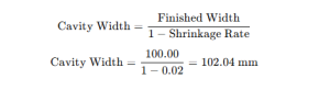
By building the mold to 102.04 mm width in that direction, the molded part will contract to approximately 100.00 mm after cooling.
Tip: Always verify the shrinkage rate through actual trial runs before cutting the final steel. Data sheet values are a good starting point, but can vary with processing parameters.
Safety and Environmental Considerations
Processing HDPE is relatively safe compared to many engineering plastics, but good practices still matter—both for operator safety and for ensuring the material’s performance and recyclability.
1. Processing Safety
Processing safety with HDPE starts with temperature control. When the melt temperature climbs above about 270 °C, the material begins to degrade, releasing fumes that can irritate operators and affect part quality. That’s why processors keep the melt within the recommended 180–230 °C range and avoid leaving material sitting in the barrel too long.
Good ventilation is just as important, especially in high-volume production where fumes can accumulate quickly. Local exhaust systems or proper machine hooding help maintain a safe workspace. And while HDPE itself is relatively safe to handle, keeping pellets clean and free of dust prevents contamination in the final parts. Many operators also wear gloves when working with regrind, since sharp edges can cause cuts during handling.
2. Recycling and Regrind Use
HDPE is one of the most widely recycled thermoplastics, labeled under the resin identification code “2.” When contamination is controlled, it can be reground and reprocessed several times with little impact on its core properties.
Many manufacturers blend regrind with virgin HDPE to cut costs and reduce environmental impact. The challenge is to choose the right ratio—too much regrind can lower mechanical strength or leave cosmetic flaws on the surface. For that reason, high-regrind blends usually end up in non-critical products like pallets or storage crates. Parts that need tight tolerances or food-contact safety, on the other hand, typically stick to virgin material or limit regrind levels carefully.
Effect of Regrind Ratio on Mechanical Properties
| Regrind Content (%) | Tensile Strength (MPa) | Impact Strength (kJ/m²) | Surface Quality | Notes |
| 0 (Virgin) | 30–33 | 60–65 | Excellent | Baseline for performance testing |
| 20 | 28–31 | 55–60 | Very good | No significant drop for most applications |
| 50 | 26–29 | 48–53 | Good | Slight color variation possible |
| 80 | 23–26 | 42–46 | Fair | Visible surface defects; not ideal for cosmetic parts |
Values are representative averages; actual results depend on grade, processing conditions, and contamination control.
Tip: If you plan to use more than 30% regrind in HDPE injection molding, run a small batch trial and measure shrinkage, mechanical strength, and surface finish before committing to full production. This ensures you balance sustainability goals with product performance.
Final Thoughts
High-quality HDPE molding depends on matching material grade, part design, process window, especially shrinkage control, cooling balance, and flow/gating strategy. Small changes in wall thickness, mold temperature, or gate design can materially affect cycle time, scrap, and dimensional consistency.
If you need tight tolerances, high-volume stability, or specialty HDPE grades, see Kemal’s HDPE injection molding services. Send your CAD and requirements for a fast DFM review and quote.