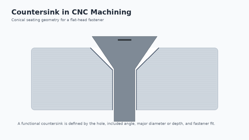
Quick answer: Most grooves are produced by CNC turning or milling. Rotational parts typically use external, internal, or face grooving, while prismatic and non-circular features are usually milled. A production-ready drawing should define the groove function, location, width, depth or bottom diameter, corner radii, critical tolerances, surface finish, and edge condition.
For broader process and capability context, see Kemal’s CNC machining services . This guide focuses specifically on selecting a groove type and tool, designing for access and stability, preventing common defects, and planning inspection.
Groove machining creates a controlled recessed feature in a part. The groove may run around a turned diameter, inside a bore, across a face, or along a milled surface. Typical functions include locating a retaining ring, holding an O-ring or seal, providing thread or grinding relief, guiding a component, carrying lubricant, or creating assembly clearance.
The geometry may look simple on a drawing, but manufacturability depends on more than nominal width and depth. Tool access, corner radius, side-wall form, chip evacuation, material behavior, workpiece stiffness, burr requirements, and inspection access can determine whether the feature is stable, measurable, and economical.
What Is Groove Machining?
Groove machining is the controlled removal of material to create a narrow recessed channel. On a shaft or bore, a lathe tool normally feeds radially or axially. On a milled component, a rotating cutter follows a programmed path to create a straight, curved, closed, or profiled groove.
The feature name alone is not enough to select a process. The manufacturer needs to know what the groove does and which dimensions or surfaces control that function.
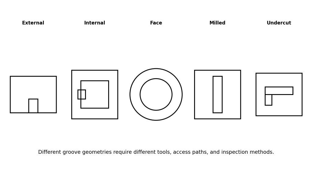
- Circumferential groove on an outside diameter
- Internal groove inside a bore
- Face groove on the end of a rotational part
- Straight or curved groove on a flat or 3D surface
- Seal or O-ring gland
- Retaining-ring or snap-ring groove
- Thread-relief, grinding-relief, or tool-clearance undercut
- Lubrication, fluid, or vent path
- Keyway, T-slot, dovetail, or another special-profile channel
Standard retaining-ring and seal grooves should be defined from the selected component or applicable specification. Do not copy a generic groove width and depth from an unrelated application: sealing, retention, pressure, motion, coating, mating geometry, and assembly conditions can change the requirement.
Groove vs. Slot, Undercut, Recess, and Parting
| Term | Typical meaning | Practical distinction |
| Groove | Narrow recessed channel, often functional | Can be external, internal, face-oriented, straight, curved, or profiled. |
| Slot | Elongated opening or channel, commonly milled | Usually defined by width, length, end shape, depth, and position. |
| Undercut | Recess below or behind adjacent geometry | Tool entry and withdrawal may matter more than the visible width. |
| Recess | General depressed area or pocket | Usually broader than a narrow groove and may use pocket-milling strategies. |
| Parting / cut-off | Cut through a turned workpiece | Continues to separation rather than stopping at a groove depth. |
| Keyway | Groove used with a key to transmit torque | May require milling, broaching, shaping, or EDM depending on geometry. |
Main Types of Groove Machining
External Grooving
External grooving creates a circumferential recess on the outside diameter of a rotational part. It is common for retaining rings, seals, reliefs, and assembly clearances. Access is usually better than for internal grooves, but deep or narrow features can still produce deflection, chatter, chip packing, burrs, and side-wall error.
Internal Grooving
Internal grooving creates a recess inside a bore. The holder must enter the bore, reach the groove, cut without rubbing, and withdraw without collision. Minimum bore size, holder diameter, overhang, shoulder clearance, chip evacuation, coolant delivery, and inspection access should be reviewed together.
Face Grooving
Face grooving creates a circular recess on the end face of a rotational part. Tool curvature must match the intended diameter range. A face-grooving tool used outside its qualified range can rub or interfere, and cutting conditions change with radius.
Groove Milling
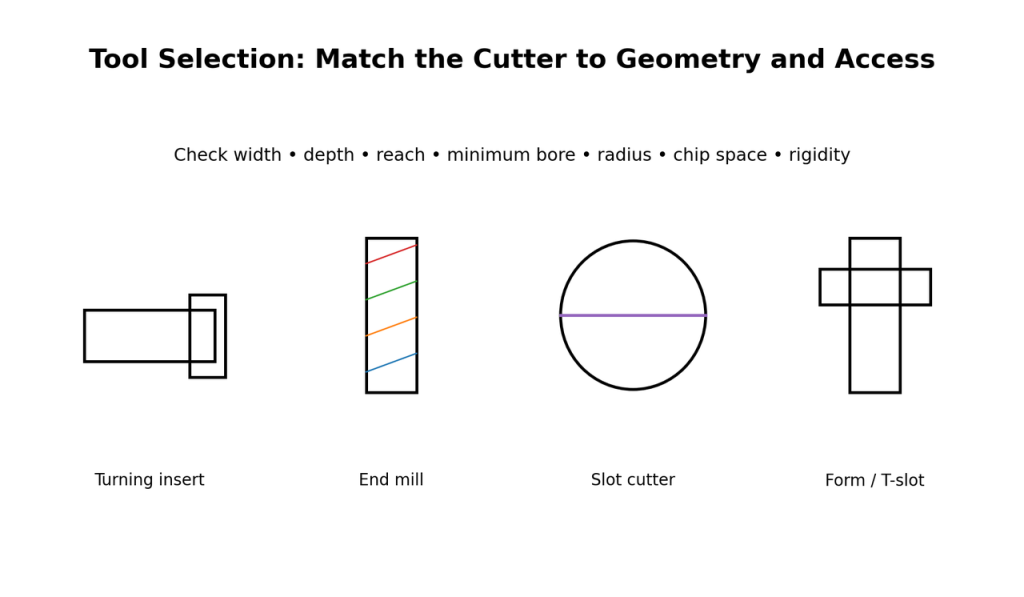
Groove milling is appropriate for straight slots, curved paths, closed grooves, key features, non-axisymmetric geometry, and profiles that cannot be produced by a simple lathe plunge. End mills, slot cutters, side-and-face cutters, keyseat cutters, T-slot cutters, dovetail cutters, and form cutters are possible choices.
When Another Process Makes More Sense
Broaching can suit controlled internal profiles when geometry and volume justify dedicated tooling. Grinding may improve finish or dimensional control on suitable hardened parts. EDM can create narrow, deep, sharp, or difficult-to-access features in conductive materials, but cost, recast layer, corner form, and electrode or wire access must be considered.
How to Choose Turning, Milling, or Another Process
| Part / groove condition | Likely process | Key question |
| Circumferential shaft groove | CNC turning | Can the tool reach the groove with sufficient rigidity? |
| Groove inside a bore | Internal CNC turning | Is the bore large enough for holder clearance, chips, and inspection? |
| Circular face groove | Face grooving / mill-turn | Does the tool diameter range suit the inner and outer groove walls? |
| Straight groove on a flat part | End milling / slot cutter | Is the groove open or closed, and what end shape is required? |
| Curved or 3D groove | CNC milling / 4- or 5-axis | Can cutter access and orientation be maintained along the full path? |
| Internal keyway | Broaching / slotting / milling / EDM | What quantity, length, corner condition, and through-access apply? |
| Narrow/deep groove in hardened material | Grinding / EDM may be evaluated | What finish, tolerance, heat-treatment, and access limits apply? |
Tool Selection for Groove Machining
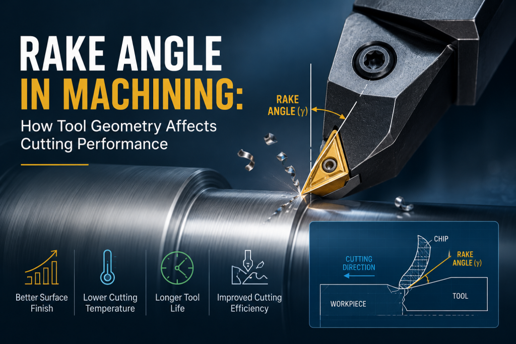
Tool selection should start from the finished geometry and access path, not from the machine alone. For turning, the insert and holder must match groove orientation, width, depth, minimum bore, corner radii, reach, chip-control needs, and coolant delivery. For milling, cutter diameter, flute length, neck clearance, arbor clearance, entry method, and chip space become equally important.
Turning Tools and Inserts
- Groove width and depth
- External, internal, or face orientation
- Minimum bore and holder clearance
- Tool reach and overhang
- Material and heat-treatment condition
- Required root and corner radii
- Chipbreaker and coolant strategy
- Whether the tool must plunge, finish, profile, or side-turn
- Machine rigidity and workholding
A wider insert can be stiffer but increases cutting load. A narrower insert can reduce load and provide more width-adjustment flexibility, but a wide groove may then need multiple passes. Keep overhang as short as practical while preserving approach and withdrawal clearance.
Milling Cutters
A cutter exactly equal to final groove width can be efficient, but runout, deflection, wear, and machine behavior may make width control difficult. A smaller cutter with controlled side passes can leave stock for finishing and make final width easier to adjust. Side-and-face or form cutters can improve productivity for open grooves when arbor and side clearance are available.
Standard vs. Custom Tools
Standard inserts and cutters reduce replacement risk and are easier to qualify. Custom form tools can combine several surfaces or reduce cycle time, but they add tooling lead time, replacement planning, and requalification. For low-volume or evolving designs, geometry that accepts standard tools is usually more flexible.
Groove Machining Strategies
| Strategy | Best fit | Main caution |
| Single plunge | Narrow groove matching insert width | Full-width engagement can increase load and chip-control difficulty. |
| Multiple plunges | Wide turned groove | Sequence passes to avoid trapped chips and unstable thin webs. |
| Rough + finish | Tight width, bottom, wall, radius, or finish requirements | Leave controlled stock and finish both walls consistently. |
| Profiling / side turning | Wider recess with approved grooving system | Not every insert is designed for lateral cutting. |
| Adaptive / trochoidal milling | Deep or difficult milled grooves | Tool diameter, entry, control, and material must support the path. |
| Staged machining | Thin walls, slender shafts, rings, soft plastics | Operation order and support may matter more than nominal tool accuracy. |
Chip Control, Coolant, and Process Stability
Grooving concentrates cutting load in a confined space. In internal and deep grooves, chips may have less exit space than the cutting zone itself. Recut chips can scratch finished walls, jam the tool, break an insert, or create unstable cutting force.
- Use chip-control geometry suited to the material and groove width.
- Direct coolant into the cutting zone where the tool system allows it.
- Keep tool overhang short and workholding rigid.
- Provide safe withdrawal and clearance moves.
- Avoid repeated dwell or rubbing on work-hardening materials.
- Inspect chip shape and insert wear during process qualification.
There is no universal speed-and-feed table for groove machining. Insert geometry, grade, holder, material, groove width and depth, coolant, machine condition, and workholding interact. Start from qualified toolmaker guidance and validate the actual setup.
Material-Specific Considerations
| Material | Typical risk | What to evaluate |
| Aluminum alloys | Built-up edge, burrs, soft-wall deformation, chip packing | Sharp geometry, controlled edge condition, effective evacuation. |
| Carbon / alloy steel | Heat, load, long chips, wear after heat treatment | Insert grade, chipbreaker, rigidity, and coolant. |
| Austenitic stainless steel | Work hardening, heat, stringy chips, notch wear | Stable cutting action; avoid rubbing and dwell. |
| Hardened steel | Wear, chipping, finish and dimensional stability | Hard turning, grinding, or EDM depending on geometry. |
| Titanium alloys | Heat concentration, wear, chip control, deflection | Rigid setup, controlled engagement, effective coolant. |
| Engineering plastics | Burrs, heat, elastic recovery, clamping deformation | Sharp tools, heat control, and defined inspection restraint. |
How to Design a Machinable Groove
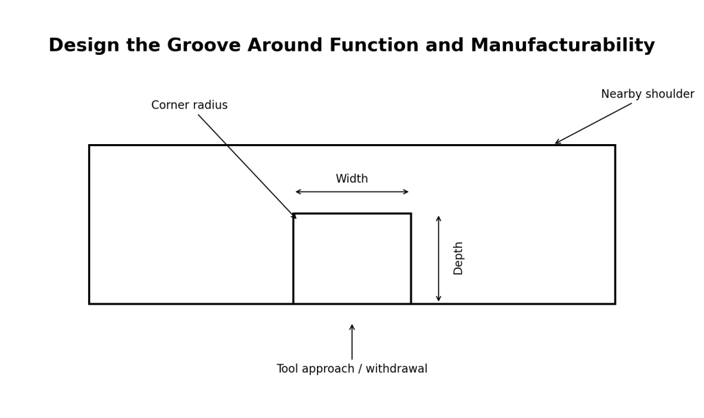
The most useful DFM review happens before the groove dimensions are frozen. Define what the feature must do, then give the manufacturing process enough freedom to use a stable tool and a measurable geometry.
1. Define Function Before Dimensions
State whether the groove retains a component, seals pressure, provides relief, guides motion, carries lubricant, or only creates clearance. Function helps determine which dimensions, surfaces, radii, and edge conditions are actually critical.
2. Use a Practical Groove Width
Very narrow grooves require thinner tools with lower stiffness and less chip space. If the function permits, select a width compatible with available standard tooling and avoid tightening width tolerance beyond the assembly or sealing requirement.
3. Control Depth-to-Width Ratio and Reach
Deep, narrow features increase deflection, heat, chip-evacuation difficulty, and inspection complexity. For internal grooves, review the complete holder path through the bore—not only the insert width at the groove.
4. Allow a Feasible Bottom and Corner Radius
Conventional cutting edges have a finite radius. Instead of requesting an undefined “sharp corner,” specify the maximum permissible root radius or the functional clearance required by the mating component.
5. Check Nearby Walls and Shoulders
The insert may fit while the holder does not. Shoulders, flanges, threads, bore transitions, and adjacent walls can block approach or withdrawal and force excessive overhang.
6. Protect Thin Walls and Slender Sections
A deep groove can reduce shaft stiffness or distort a thin ring. Remaining wall thickness, clamping force, residual stress, heat treatment, operation sequence, and finish allowance should be considered together.
7. Design for Inspection
A groove can be machinable but difficult to measure. Narrow internal grooves are especially sensitive to gauge access and contact geometry. Agree on how width, bottom diameter, location, radius, finish, and functional fit will be verified before production.
DFM checkpoint: If your groove is deep, narrow, internal, seal-critical, close to a shoulder, or located on a thin wall, submit the CAD model, drawing, material, quantity, groove function, and critical tolerances. Kemal’s engineering team can review tool access, burr and distortion risks, inspection method, and the appropriate CNC machining route before quotation.
How to Specify a Groove on an Engineering Drawing
- Feature type and orientation: external, internal, face, straight, curved, undercut, keyway, seal gland, or retaining-ring groove.
- Location: dimension from a functional datum or controlled reference surface.
- Width: state limits and where width is evaluated if walls are angled or radiused.
- Depth or bottom diameter: define the controlling radial or axial dimension and tolerance.
- Length or angular extent for non-continuous grooves.
- Bottom shape: flat, radiused, angled, or controlled profile.
- Corner and edge radii: root radius, blends, chamfers, and permitted tool radius.
- Side-wall geometry: perpendicularity, taper, angle, or profile where function requires it.
- Surface roughness on the relevant groove surfaces.
- Burr and edge condition: permitted break, chamfer, rollover, or sharpness.
- Geometric relationship to datums: position, runout, concentricity, profile, or orientation as needed.
- Applicable seal, retaining-ring, thread-relief, or company standard and revision.
- Inspection condition: free or restrained state, before/after coating, and functional-gauge or mating-component test.
Surface Finish, Burrs, and Edge Condition
Groove quality is not described by one width dimension. Seal, ring, sliding, bearing, and fluid-control grooves may depend on bottom finish, side-wall finish, feed-mark direction, root condition, burrs, and coating buildup. A single Ra value does not describe waviness, torn material, chip scratches, or rolled edges.
Deburring must also be controlled. Removing a burr should not change a critical groove width, ring shoulder, sealing edge, or radius. If the part will be anodized, plated, coated, or passivated, state whether dimensions and finish apply before or after the secondary process.
Common Groove Machining Problems and Corrective Direction
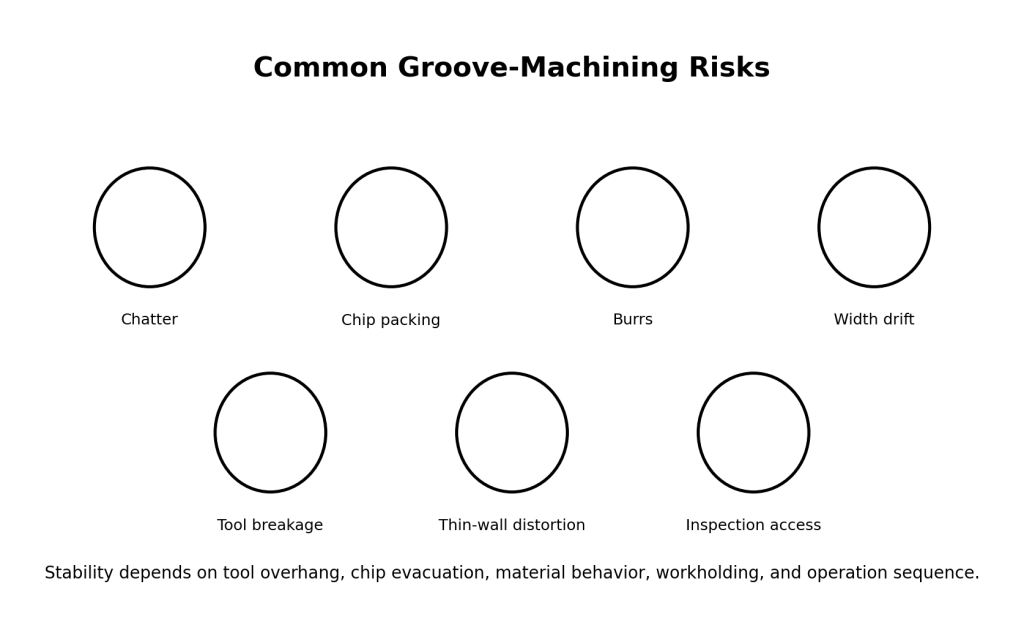
| Symptom | Factors to investigate | Corrective direction |
| Chatter / vibration | Overhang, weak support, thin tool, unstable cutting conditions | Increase rigidity, shorten reach, review support and cutting data. |
| Width oversize / taper | Deflection, runout, wear, thermal drift, inconsistent finish passes | Separate rough/finish control and verify both walls with the agreed method. |
| Poor bottom finish | Chip recutting, rubbing, damaged edge, built-up material | Improve evacuation, tool condition, coolant, and finishing engagement. |
| Burrs | Ductile material, dull tool, exit direction, unsupported edge | Use suitable edge geometry and controlled deburring. |
| Tool breakage | Chip packing, collision, wrong cutting direction, excessive load | Stop and diagnose clearance, chips, holder support, and program. |
| Part distortion | Section loss, thin wall, clamping, residual stress, heat | Change sequencing/support, leave finish stock, review inspection restraint. |
| Internal scratches | Trapped chips during cutting or withdrawal | Improve evacuation and clearance moves; inspect after retraction. |
How Groove Machining Is Inspected
Inspection should be selected by the characteristic being controlled, not by a default instrument. Width, bottom diameter, location, radius, surface finish, and functional sealing or retention may require different methods.
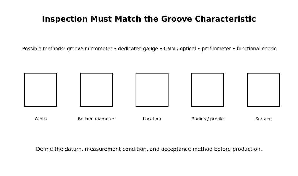
| Characteristic | Possible method | Important limitation |
| External groove width | Groove micrometer, comparator, CMM, dedicated gauge | Wall angle and contact geometry can change the reading. |
| Bottom diameter | Groove micrometer, special anvils, optical/CMM, functional gauge | Contact position and tool access must be defined. |
| Internal width / diameter | Internal groove gauge, groove micrometer, CMM/optical, master | Deep or narrow access can dominate uncertainty. |
| Face groove diameter / width | CMM, optical, height/diameter method, dedicated gauge | Alignment to the rotational datum is critical. |
| Location to datum | CMM, height gauge, comparator, qualified fixture | Datum setup must match the drawing. |
| Corner radius / profile | Comparator, vision, contour instrument, CMM where suitable | Magnification, point density, and edge definition matter. |
| Surface roughness | Profilometer or qualified optical method | Cutoff, direction, stylus size, and access must be specified. |
| Functional sealing / retention | Approved ring/seal, master, leak/pressure or functional test | Test conditions and acceptance limits must be controlled. |
A dimensional report alone does not prove sealing or retention if the mating component, burr, finish, coating, or functional stack is wrong. Where the application requires it, dimensional and functional verification should be planned together.
What Drives Groove Machining Cost and Lead Time?
- Groove orientation, entry, and withdrawal access
- Depth-to-width ratio and tool reach
- Internal-bore diameter and holder clearance
- Special profiles or custom tooling
- Material grade, condition, and heat treatment
- Tight width, diameter, location, or profile tolerances
- Surface-finish and burr requirements
- Thin-wall support, soft jaws, or extra setups
- Chip-control difficulty and tool life
- Coating allowance and post-process inspection
- Dedicated gauges, first-article reports, or functional testing
- Quantity and repeatability requirements
A wide tolerance does not automatically make a deep internal groove inexpensive: access and chip evacuation can still dominate process risk. Conversely, a tight but accessible groove can be efficient when it matches qualified tooling and inspection.
Information Required for a Groove Machining RFQ
Send a controlled project package rather than only a screenshot of the groove. The following information lets an engineering team evaluate tool access, inspection, and quotation with fewer assumptions:
- 3D CAD model and toleranced 2D drawing with matching revisions
- Material grade, condition, and heat treatment
- Part quantity and expected repeat demand
- Groove function and orientation
- Width, depth or bottom diameter, location, radii, and surface requirements
- Mating seal, retaining ring, key, or component specification
- Critical tolerances and CTQ characteristics
- Burr, edge-break, cleaning, and cosmetic requirements
- Coating, plating, passivation, anodizing, or other secondary process
- Inspection method, sampling plan, and report requirements
- Functional test and acceptance condition where applicable
Request a manufacturability review: Submit the groove drawing/CAD file, material, quantity, and critical tolerances. Kemal can evaluate the tool approach, minimum bore or shoulder clearance, likely machining route, measurement method, and quotation through its CNC machining service.
Questions to Ask a Groove-Machining Supplier
- Which process and machine will create the groove, and why?
- Is the proposed tool standard or custom, and how will replacement be handled?
- Can the holder enter, cut, and withdraw without collision or excessive overhang?
- How will chips and coolant move through the cutting zone?
- Will roughing and finishing be separated for critical dimensions?
- How will width, bottom diameter/depth, location, radius, finish, and burr be inspected?
- Does the groove follow the specified seal, ring, or component standard and revision?
- Which characteristics require first-article, sampling, or functional testing?
- How will coating, heat treatment, or part distortion affect the final groove?
- Which DFM changes require buyer approval?
Frequently Asked Questions
What is groove machining?
Groove machining removes material to create a controlled recessed channel. It may be turned on an outside diameter, inside a bore, or on a face, or milled along a straight, curved, or profiled path.
What is the difference between grooving and parting?
Grooving stops at a specified depth or diameter to create a recess. Parting continues through a turned workpiece to separate it.
What is the difference between a groove and a slot?
The terms overlap. “Groove” often emphasizes a functional recess, while “slot” often describes an elongated milled channel. The drawing geometry and function are more important than the name.
Which tools are used for groove machining?
Common tools include grooving inserts and holders, end mills, slot and side cutters, keyseat cutters, T-slot cutters, and form tools. Geometry, access, material, tolerance, and quantity determine the choice.
Why do grooving tools break?
Common causes include chip packing, excessive overhang, poor support, collision, unsuitable cutting direction, unstable conditions, worn edges, and insufficient clearance.
How are internal grooves inspected?
Possible methods include internal groove gauges or micrometers, CMM or optical systems, dedicated masters, and functional components. The correct method depends on access, width, bottom diameter, tolerance, and function.
Can a groove have a sharp internal corner?
Conventional cutting tools have a finite edge radius. Define the maximum acceptable radius or functional clearance; consider another process only when the requirement justifies it.
What files are needed for a groove-machining quote?
Provide CAD and a controlled drawing, material and condition, quantity, groove function and dimensions, mating component or standard, tolerances, finish, burr requirements, secondary processes, and inspection or functional-test requirements.
Conclusion
Successful groove machining starts with a complete functional definition. Groove orientation, tool access, width and depth, corner radius, material, chip evacuation, part stiffness, burr control, surface finish, inspection, and assembly behavior must be considered as one manufacturing problem—not as isolated drawing dimensions.
For a project-specific review, submit the CAD model, drawing, material, quantity, groove function, mating component, and critical tolerances. The engineering review should confirm tool accessibility, likely process, inspection method, and any DFM changes before quotation.