Quick answer: Flow lines are waves, rings, or streaks that follow the melt-flow pattern on injection-molded parts. They often result from uneven melt flow or cooling caused by temperature, injection speed, gating, wall-thickness changes, venting, or material issues. Troubleshooting should begin with filling and thermal conditions before moving to material, tooling, or part-design changes.
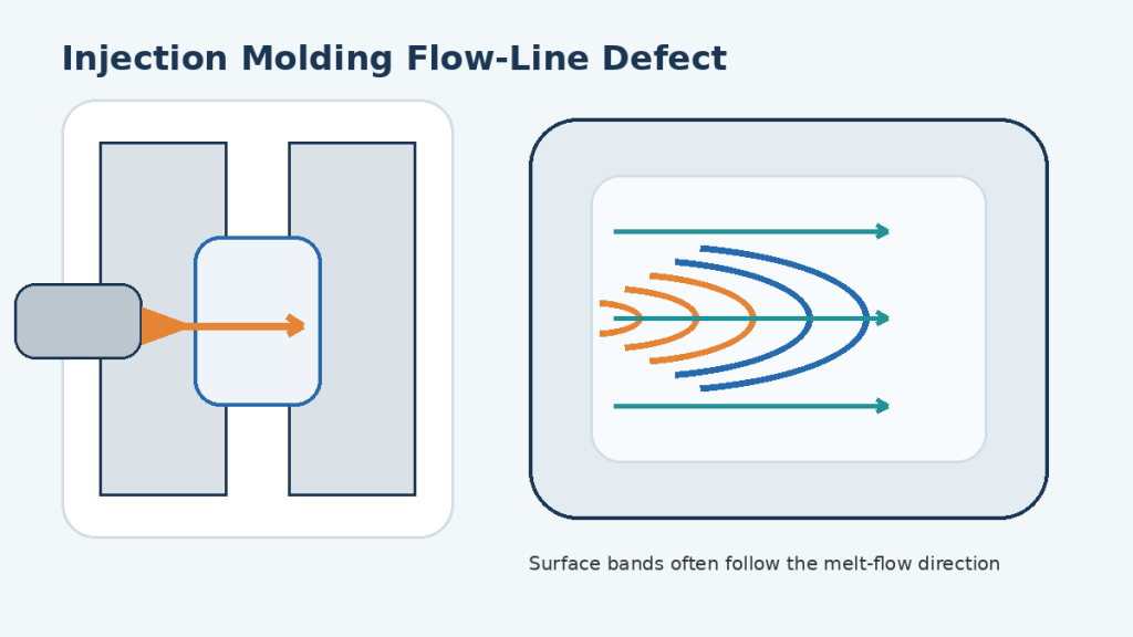
Flow lines are often treated as a cosmetic issue, but in production they are also a useful signal. Their location and shape can show where the melt slowed, hesitated, cooled too early, changed direction, or encountered a restriction. That makes the defect valuable diagnostic evidence rather than something to hide with texture or a secondary finish.
If you are troubleshooting a broader set of surface or filling problems, start with Kemal’s common injection molding defects guide and then use this article to isolate flow-line-specific causes.
What This Guide Covers
- How to recognize flow lines and separate them from jetting, weld lines, splay, burn marks, and gate blush.
- How melt temperature, mold temperature, fill speed, packing, gate design, wall thickness, venting, and resin condition create the defect.
- A practical troubleshooting sequence that starts with low-cost process changes and escalates to tool or part modifications only when necessary.
- What evidence to collect before requesting an engineering diagnosis or transferring a mold to another supplier.
What Are Flow Lines in Injection Molding?
Flow lines, also called flow marks, are surface patterns that become visible because different regions of the polymer skin formed under different flow or cooling conditions. They commonly appear as wavy bands, circular or semicircular rings near a gate, fingerprint-like ripples, or repeated changes in gloss or color. In many cases the pattern follows the direction in which the melt front moved through the cavity.
During normal filling, molten polymer advances with a fountain-flow behavior: material near the center of the flow front moves forward and then turns outward toward the colder mold wall. A thin frozen layer forms at the surface while hotter material continues through the core. If the melt front slows down, cools prematurely, changes velocity sharply, or receives a slug of colder material, that skin can record the interruption as a visible band.
Flow lines are usually an appearance defect, but do not assume they are harmless in every application. A visible line may be confused with a weld line, contamination streak, delamination, or local filling problem that has different functional implications. The first troubleshooting task is therefore defect identification, not parameter adjustment.
How to Identify Flow Lines—and Not Misdiagnose a Different Defect
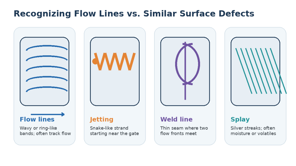
| Defect | Typical appearance | Where it appears | Diagnostic clue |
| Flow lines / flow marks | Wavy, ring-like, fingerprint-like, or repeated gloss/color bands | Often near the gate, at a thickness transition, or along a long flow path | Pattern usually relates to melt-flow direction and changes with thermal or fill conditions |
| Jetting | Snake-like or rope-like strand | Usually starts directly from the gate into an open cavity region | Often linked to a high local gate velocity or gate direction that lets the melt jet instead of forming a stable fountain front |
| Weld line | Thin seam, notch, or local color line | Where two melt fronts meet after splitting around a hole, core, insert, or multiple gates | Location follows where fronts rejoin; may affect strength as well as appearance |
| Splay / silver streaks | Fine silver or whitish streaks, often feathered | Can extend away from the gate or along flow | Check moisture, volatiles, degradation, shear, or contamination |
| Gate blush | Cloudy or discolored patch concentrated around the gate | Immediately around the gate | Often related to gate shear, local temperature, or velocity rather than a downstream fill interruption |
| Burn mark | Brown, black, or charred discoloration | Commonly near end-of-fill or trapped-air locations | Points toward trapped gas, poor venting, or excessive local temperature/shear |
If the line forms where two flow fronts meet, review weld-line causes and prevention before treating it as a conventional flow mark.
Why Flow Lines Form: The Root-Cause Chain
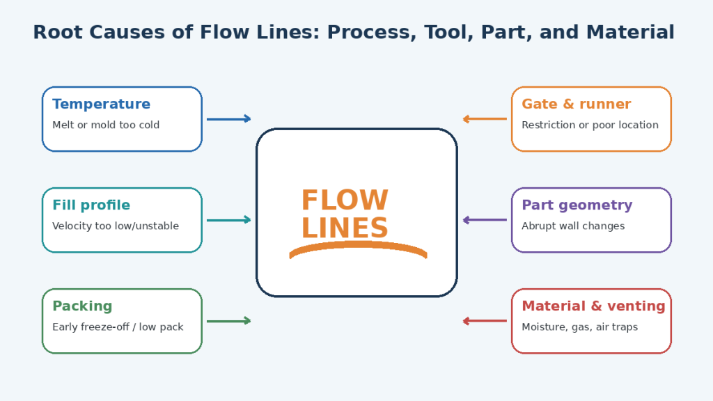
The visible mark is the end result of a chain rather than a single parameter. A useful way to diagnose the problem is to ask four questions: Was the melt hot enough? Did the melt front keep moving at a controlled rate? Did the tool and part geometry support that flow? Was the material in a stable, processable condition?
1. Melt Temperature Is Too Low or Unstable
If the real melt temperature is too low, viscosity rises and the advancing skin freezes sooner. The melt front may then hesitate or leave a ripple pattern as hotter material pushes against a partly solidified surface layer. A low nozzle temperature or an unbalanced barrel profile can create the same symptom even when the machine setpoint looks reasonable.
- Verify actual melt temperature using an appropriate measurement method; do not rely only on barrel setpoints.
- Check whether the nozzle or front zone is creating a cold slug that enters the cavity at the beginning of injection.
- Increase melt temperature only within the resin supplier’s recommended processing window; excessive temperature can create degradation, gas, discoloration, or splay.
2. Mold Temperature Is Too Low or Uneven
A cold cavity surface freezes the polymer skin quickly. This is especially visible on glossy, cosmetic, thin-wall, or long-flow-path parts where small changes in surface replication are easy to see. Uneven cooling can also make one cavity or one region of a large part behave differently from another.
For a deeper explanation of thermal stability, see how mold temperature control affects injection molding quality.
- Confirm mold inlet and outlet temperatures and look for circuit imbalance, scale, blocked channels, or uneven contact at inserts.
- Raise mold temperature in controlled increments if the material and cycle allow it, then watch whether the flow pattern becomes less visible and more repeatable.
3. Injection Speed or Velocity Profile Is Too Slow—or Changes at the Wrong Place
A slow or poorly staged fill gives the melt more time to lose heat before reaching the end of the cavity. But “increase speed” is not a universal rule. Very high local velocity through a small gate can create excessive shear, gate blush, or jetting. The objective is a stable fill profile that keeps the flow front moving without abrupt acceleration or deceleration.
- Compare fill time, not just machine speed percentages, between good and bad cycles.
- Use staged velocity when geometry changes significantly so the flow front does not suddenly race through a thin region or stall at a thick-to-thin transition.
- If the mark moves when the velocity transition position changes, the fill profile is likely part of the cause.
4. Injection Pressure, V/P Transfer, or Packing Is Not Supporting the Flow
The machine must supply enough pressure to achieve the selected velocity through the runner, gate, and cavity. If the process becomes pressure-limited, actual velocity drops even though the programmed speed remains high. Early V/P transfer can also leave part of the cavity under-filled before packing begins.
Packing influences surface replication near the gate and can preserve or reduce a flow pattern depending on gate freeze and local pressure. However, packing should not be used to compensate for a fundamentally poor filling pattern.
- Check peak injection pressure and whether the machine is hitting a pressure limit during first-stage fill.
- Verify V/P transfer position, cushion consistency, and part weight before changing pack pressure.
- Use a gate-freeze study when necessary to confirm how long packing can influence the cavity.
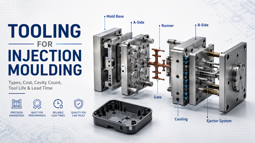
5. Gate, Runner, Nozzle, or Cold-Slug Design Restricts the Melt
A small gate, long restrictive runner, undersized sprue, poor gate orientation, or cold material entering the cavity can force the melt front to slow and cool. Gate location also determines flow length, direction, weld-line position, air traps, and whether the melt reaches cosmetic surfaces with enough temperature.
- Inspect the mark’s distance from the gate. Repeated rings close to the gate often point toward early cooling, cold material, or local gate conditions.
- Check for a functional cold-slug well in cold-runner systems and confirm the nozzle is not producing excessive cold material.
- If process optimization cannot produce a robust window, evaluate gate size, type, direction, and location rather than continuing to increase pressure.
6. Abrupt Wall-Thickness Changes Cause Hesitation or Flow-Velocity Shifts
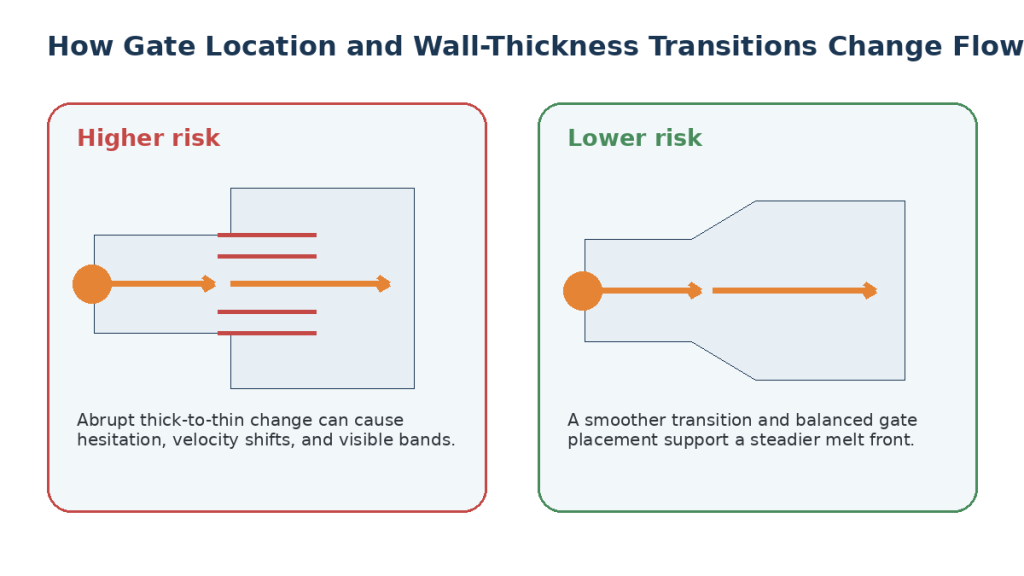
The melt does not move through every thickness at the same rate. Sudden changes in cross section alter local resistance, cooling rate, shear, and the path of least resistance. A melt front may race ahead through one region while hesitating in another, leaving visible bands when the fronts stabilize again.
This is why uniform wall thickness and gradual transitions are important not only for sink and warpage control but also for stable filling.
- Use gradual transitions instead of abrupt thick-to-thin steps where the product design permits.
- Review ribs, bosses, windows, and local thick pads that may redirect the melt front.
- Use mold-flow simulation before cutting steel when gate location and long flow paths are likely to interact with wall transitions.
7. Venting Is Inadequate or an Air Trap Is Disturbing the Melt Front
Poor venting is not always the first cause of a conventional flow mark, but trapped air can slow the melt front, compress at the end of fill, create local heating, or force the polymer to change direction. This is particularly relevant when the visible line consistently appears near the end of fill, around a rib cluster, or in a closed-off pocket.
- Inspect parting-line vents, ejector-pin vents, inserts, and end-of-fill regions for contamination or blocked vent depth.
- If a dark burn accompanies the line, prioritize air-trap and venting checks over simply raising melt temperature.
8. Material Condition, Moisture, Regrind, or Colorant Is Changing Flow Behavior
Resins differ in viscosity, shear sensitivity, crystallization behavior, filler content, moisture sensitivity, and surface appearance. Even when the nominal material grade is unchanged, drying, lot variation, regrind level, masterbatch concentration, or contamination can move the process outside the stable window.
- Confirm the exact resin grade, lot, colorant, filler content, and approved regrind percentage.
- Follow resin-supplier drying requirements for moisture-sensitive materials and record dryer dew point, time, and temperature where relevant.
- Compare a known-good virgin-material run when contamination or regrind is suspected.
How to Fix Flow Lines in Injection Molding: Use the Right Troubleshooting Order
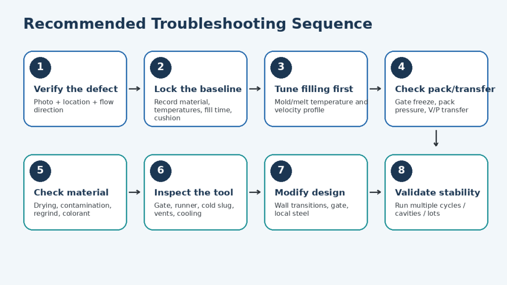
The most expensive troubleshooting mistake is changing several variables at the same time. A part may improve, but the team no longer knows why; the defect then returns when the material lot, ambient conditions, machine, or mold changes. A better sequence isolates the mechanism and leaves a repeatable process window.
Step 1: Verify the defect and map its location
Photograph the defect under consistent lighting. Mark the gate, flow direction, end-of-fill, weld lines, thickness transitions, and cavity number. If possible, compare a good part and a bad part from the same tool. The exact location often narrows the cause faster than the appearance alone.
Step 2: Lock and document the current baseline
Record resin grade and lot, drying conditions, barrel and nozzle setpoints, actual melt temperature if available, mold temperature, fill time, injection pressure, V/P transfer, cushion, pack profile, cycle time, part weight, and cavity number. Save the baseline before changing anything.
Step 3: Correct the thermal and filling conditions first
Within the resin and tool limits, stabilize mold temperature, verify melt temperature, and adjust the injection-velocity profile so the melt front stays active through the cavity. Change one factor at a time or use a structured DOE if the process has multiple interactions.
Step 4: Verify transfer and packing
Confirm that the cavity is substantially filled before V/P transfer, that the process is not unintentionally pressure-limited, and that pack pressure and time are adequate without overpacking. Watch cushion and part weight to verify shot-to-shot consistency.
Step 5: Eliminate material variability
Check drying, contamination, regrind, masterbatch, and lot changes. If the defect appeared after a resin or color change, run a controlled comparison before modifying the tool.
Step 6: Inspect the tool and cooling circuits
Check gate condition, runner restriction, cold-slug control, vents, cooling-channel balance, heater function in hot-runner systems, and any maintenance condition that could have changed since the last good production run.
Step 7: Modify the gate, local steel, or part geometry only when needed
If a stable process window cannot be established, the issue may be structural: gate location, gate size, long flow length, abrupt wall change, trapped air, or a cooling-layout limitation. Tool changes should be based on the observed fill pattern and, for difficult parts, validated with simulation or a controlled mold trial.
Step 8: Validate the correction over time
Do not approve a fix based on five good shots. Confirm the defect stays within acceptance criteria after the mold reaches thermal equilibrium and across the relevant cavities, material lots, operators/shifts, and normal process variation.
Flow-Line Corrective Action Matrix
| Observed pattern | Likely first checks | Low-cost trial | If not resolved | Watch-out |
| Rings or ripples close to gate | Melt/nozzle temperature, mold temperature, cold slug, gate restriction | Stabilize temperature; optimize early fill velocity | Review cold-slug well, gate size/orientation | Too much velocity can create jetting or blush |
| Wavy bands after a wall transition | Fill profile, thickness change, flow hesitation | Stage velocity through transition; stabilize mold temperature | Modify wall transition or gate location | Do not mask an unstable fill with excessive pack |
| Marks near end of fill | Fill time, pressure limit, venting, mold temperature | Increase controlled fill rate; check pressure reserve | Improve vents, gate/runner balance, or cooling | Raising temperature may worsen burns if gas is trapped |
| Only one cavity affected | Cavity gate, vent, cooling circuit, local steel condition | Compare cavity pressure/fill behavior and clean vents | Balance gate/runner or repair local cooling/tool condition | Avoid changing global settings to fix a local cavity issue |
| Defect appears after material/color change | Drying, viscosity, additives, masterbatch, lot | Run known-good material under baseline conditions | Re-establish process window or review material specification | Do not assume the old process is transferable across grades |
| Intermittent lines after several cycles | Thermal drift, dryer stability, hot-runner variation, cushion/shot consistency | Trend mold temperature, fill time, cushion, part weight | Service temperature control, non-return valve, heaters, or cooling | Intermittent defects require trend data, not a single snapshot |
Use the Defect Location to Narrow the Cause
Flow Lines Near the Gate
Prioritize nozzle/front-zone temperature, mold temperature near the gate, cold-slug control, gate geometry, and the first stage of the velocity profile. If the pattern is rope-like rather than wavy, rule out jetting before raising velocity further.
Flow Lines at a Rib, Boss, Window, or Thickness Change
Look for hesitation, race tracking, and local changes in shear or cooling. Adjusting the velocity profile can prove the mechanism, but a permanent fix may require a smoother wall transition, gate relocation, or local geometry change.
Flow Lines Far from the Gate or Near End of Fill
Check whether the melt is losing too much heat or pressure along the flow path. Review fill time, pressure reserve, mold temperature, venting, and gate/runner restriction. Long flow length combined with thin walls is more likely to need a tooling or design change if the process window is narrow.
Flow Lines in Only One Cavity
This usually deserves a cavity-specific investigation before global process changes. Compare gate dimensions, vent cleanliness, cooling performance, insert temperature, runner balance, and cavity fill time. A global temperature or speed increase may improve the bad cavity while pushing the other cavities toward flash or overpacking.
When Process Changes Are Not Enough: Mold and Part Corrections
A robust production process should not depend on an extreme temperature, pressure, or speed setting just to hide the defect. If acceptable parts exist only in a very narrow process window, the tool or product design may be driving the problem.
- Enlarge or reshape a restrictive gate when pressure loss and local cooling are excessive.
- Relocate or redirect the gate to shorten the flow path, avoid direct jetting, or move a visible flow pattern away from a critical cosmetic surface.
- Add or restore venting at the end of fill or around trapped-air regions.
- Improve runner balance in multi-cavity tools when cavity-to-cavity fill behavior differs.
- Modify local wall transitions, ribs, or thick sections where the melt repeatedly hesitates.
- Review cooling-channel layout or local insert temperature where the surface freezes too quickly or thermal balance is poor.
Permanent tooling corrections can require insert rework, gate/runner machining, local steel changes, or new mold components. See Kemal’s mold manufacturing capabilities for tooling context. Where mold inserts or related precision components require subtractive machining, the CNC machining service is also relevant.
How to Prevent Flow Lines Before the Mold Is Built
Preventing the defect during DFM is usually cheaper than tuning around it after steel is cut. The goal is to reduce sudden changes in flow resistance and to keep the melt front hot, balanced, and vented across the cavity.
- Keep nominal wall thickness as uniform as the product requirements allow and use gradual transitions between different sections.
- Place gates so the melt reaches critical cosmetic surfaces with a stable flow front and without an unnecessarily long path.
- Avoid gate directions that inject a high-speed stream directly into a large open cavity where jetting can occur.
- Provide adequate runner/gate cross section and cold-slug control for the selected resin and shot size.
- Identify end-of-fill zones and likely air traps, then design venting access before the first mold trial.
- Plan cooling circuits for uniform mold-surface temperature, especially around thick sections and cosmetic faces.
- Use flow simulation for complex geometry, multiple gates, thin walls, long flow paths, family molds, or demanding appearance requirements.
For projects where gate location, wall thickness, or flow balance are still open, Kemal’s mold design service provides a more appropriate next step than trying to solve the problem after production tooling is finished.
How to Validate That the Flow-Line Fix Is Production-Ready
A correction is complete only when it is repeatable. For cosmetic parts, establish a visual acceptance standard before the next mold trial or production run. Use controlled lighting, viewing angle, distance, and master samples where possible. For parts with multiple cavities, record cavity identification so a local defect does not disappear inside an overall scrap rate.
- Allow the mold and temperature-control system to reach thermal equilibrium before final approval.
- Verify multiple consecutive cycles rather than isolated samples.
- Compare part weight, fill time, cushion, and relevant process trends between approved and rejected parts.
- Confirm the process has reasonable margin before flash, burn, jetting, short shot, or material degradation begins.
- Document the approved process window and any tool-maintenance conditions such as vent cleaning.
What to Send for a Flow-Line Engineering Diagnosis
The fastest diagnosis comes from evidence that connects the visible defect to the mold and process. If you are requesting troubleshooting support, a mold transfer review, or a new injection molding quote, send as much of the following as available:
- Clear defect photos showing the full part, a close-up, the gate location, and the defect under consistent lighting.
- 2D drawing and 3D CAD model, including cosmetic surfaces and any appearance acceptance criteria.
- Exact resin grade, color, filler/additive content, drying specification, regrind percentage, and recent material changes.
- Mold information: cavity count, runner type, gate type/location, mold age or shot count if known, recent repairs, and known vent/cooling issues.
- Machine and process data: barrel/nozzle temperatures, mold temperatures, fill time, injection velocity profile, peak pressure, V/P transfer, pack pressure/time, cushion, cooling time, and cycle time.
- A short timeline: when the defect first appeared, whether it occurs in every cavity, and what changes have already been tried.
Need help diagnosing flow lines on a real part?Upload the defect photos, part drawing/CAD, material grade, mold information, and molding parameters. Kemal can use that information to review whether the first correction should be process tuning, material control, mold maintenance/modification, or a new tooling/production plan. View injection molding services>> |
Frequently Asked Questions About Flow Lines in Injection Molding
Are flow lines the same as weld lines?
No. Flow lines are generally waves, rings, or surface bands caused by changes in flow and cooling. A weld line forms where two separate melt fronts meet. A weld line may affect mechanical performance, while a conventional flow mark is more often cosmetic.
Can increasing injection speed remove flow lines?
It can when the melt front is cooling or slowing too much, but speed should be changed with the defect mechanism in mind. Excessive local velocity can create jetting, gate blush, high shear, flash, or burns. The target is a stable velocity profile, not simply the highest possible speed.
Does higher mold temperature always improve flow marks?
A warmer mold often delays skin freeze and improves surface replication, but the correct range depends on the resin, part, tool, cycle target, and other quality requirements. Excessive mold temperature can lengthen cooling and affect shrinkage or dimensional stability.
Why do flow lines appear only after changing color or material lot?
A new masterbatch, pigment loading, moisture condition, filler content, regrind level, or lot viscosity can change flow and surface appearance. Restore the previous baseline with known-good material before deciding that the mold needs modification.
Can flow lines be polished or textured out?
Texture may make a minor cosmetic pattern less visible, but it does not correct an unstable filling condition. If the underlying problem changes with temperature, velocity, cavity, or material lot, fix the process or tool before using texture as an appearance strategy.
When should mold-flow analysis be used?
Use it when the likely correction involves gate location, multiple gates, thin walls, long flow length, abrupt thickness changes, air traps, family molds, or repeated tool rework. Simulation is most valuable before steel changes, when several geometry options need to be compared.
What is the fastest way to get a useful supplier diagnosis?
Send photos plus the CAD/drawing, exact resin grade, gate and cavity information, and the current molding setup. A photo without process data usually supports only a broad list of causes; the combined evidence makes it possible to rank the likely causes and choose a controlled trial sequence.
Conclusion
Flow lines in injection molding are evidence that melt flow, cooling, pressure, tooling, geometry, or material behavior is not fully stable. Identify the defect and map its location first; then stabilize melt and mold temperature, verify the fill profile and pressure reserve, check V/P transfer and packing, eliminate material variability, and inspect the gate, runner, venting, and cooling system. Modify the mold or part only when a robust process window cannot be established. For an active defect, send the photos, CAD or drawing, resin specification, mold details, and current process sheet so the root-cause review can begin with evidence rather than assumptions.