| Quick answer: Use a countersink when a flat-head fastener must seat on a conical surface. Match the countersink angle to the actual fastener standard, then control the feature with the pilot-hole diameter plus either the countersink major diameter or countersink depth. For purchasing, send the 2D drawing, 3D model, material, quantity, fastener specification, and any flushness or inspection requirement. |
A countersink is a conical recess at the entrance of a hole, most often used so a flat-head screw, bolt, or rivet can sit flush with or below the surrounding surface. The geometry looks simple, but a production-ready countersink depends on more than choosing a cutter: the included angle must match the fastener, the major diameter or depth must control final seating, the pilot hole must provide the required clearance, and the drawing must make the inspection requirement unambiguous.
This guide explains how countersinks differ from counterbores and chamfers, how 82° and 90° angles are selected, how diameter and depth relate to fastener fit, how CNC countersinks are machined, and how engineers can specify and inspect them without adding unnecessary tolerance or cost.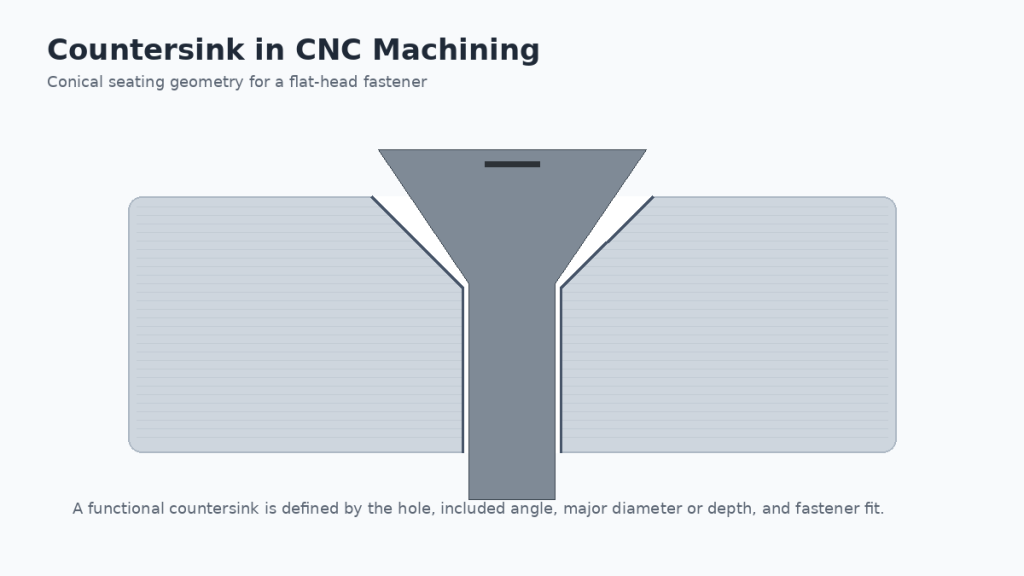
What Is a Countersink?
A countersink is a conical enlargement made at the mouth of a drilled, bored, or machined hole. Its most common purpose is to create a matching seat for a conical fastener head so the top of the fastener can finish flush with, slightly below, or at a controlled relationship to the part surface.
Countersinks are also used for deburring and edge breaking, but a functional fastener countersink should not be treated as a generic chamfer. A deburring chamfer may be acceptable if only a sharp edge must be removed. A fastener seat, by contrast, has to match a defined head angle and final head position.
- Flush fastener installation where protruding heads would interfere with mating parts, motion, sealing, handling, or appearance.
- Controlled seating for flat-head screws, bolts, or rivets.
- Lead-in or edge relief around drilled holes when the geometry is intentionally specified.
- Removal of drilling burrs when the requirement is an edge break rather than a structural fastener seat.
Countersink vs. Counterbore vs. Chamfer
Countersinks and counterbores are frequently confused because both enlarge the entrance of a hole. The difference is the shape of the recess. A countersink is conical. A counterbore is cylindrical with a flat bottom. A chamfer is a beveled edge and may or may not be associated with fastener seating.
| Feature | Geometry | Typical Purpose | Common Fastener Relationship |
| Countersink | Conical recess | Seat a conical head flush or below surface | Flat-head / countersunk fastener |
| Counterbore | Cylindrical recess with flat bottom | Recess a cylindrical head or provide a shoulder | Socket-head cap screw or similar head |
| Chamfer | Beveled edge | Deburr, edge break, lead-in, or assembly clearance | May have no fastener function |
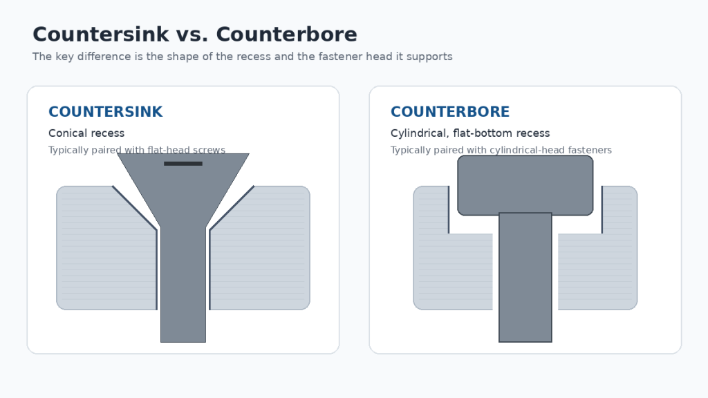
For quoting and inspection, avoid using these terms interchangeably. A note such as “break sharp edges” does not define a functional countersink, and a modeled cone without a drawing requirement may not communicate the intended fastener fit.
Common Countersink Angles: 82°, 90°, 100°, and Others
The included angle is one of the most important countersink dimensions because it determines how the fastener head contacts the seat. The angle should be selected from the fastener specification, not from a general assumption about the part or hole size.
| Included Angle | Common Use | Design Note |
| 60° | Centering features and some specialized applications | Do not substitute for a flat-head screw seat unless the fastener requires it. |
| 82° | Common for many inch-series flat-head screws | Frequently encountered in North American hardware; verify the actual screw standard. |
| 90° | Common for many metric countersunk screws | Widely used with metric flat-head/countersunk fasteners. |
| 100° | Used by some aerospace and specialized fastener families | A shallower cone can spread the head footprint over a wider area. |
| 120° | Special-purpose countersinking or chamfering | Use only when the drawing or fastener system requires it. |
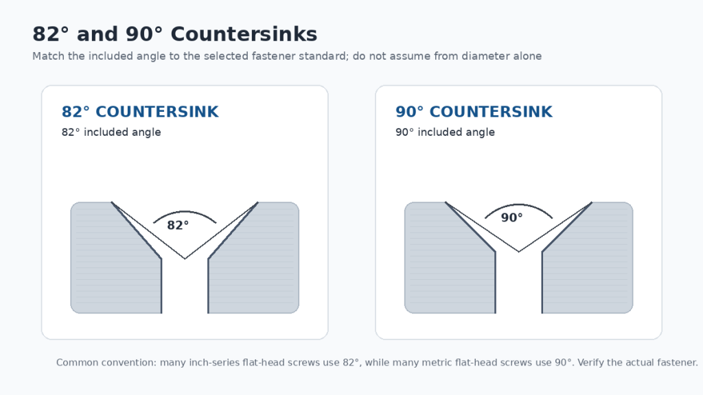
| Important: Angle mismatch can create edge contact even when the head looks nearly flush. Match the countersink angle to the actual fastener specification. |
Countersink Dimensions: Diameter, Depth, Angle, and Pilot Hole
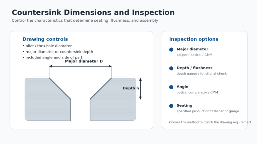
A countersink is normally defined by four geometric inputs: the pilot or thru-hole diameter, the major diameter at the part surface, the included angle, and the resulting countersink depth. In many drawings, only three of these need to be specified because the fourth is mathematically related.
- Pilot-hole diameter (d): the drilled or machined hole below the conical seat. For a clearance hole, this is selected from the fastener and assembly requirement.
- Major diameter (D): the largest diameter of the countersink where the cone meets the part surface.
- Included angle (A): the full cone angle, such as 82° or 90°.
- Countersink depth (h): the axial distance from the top surface to the point where the conical surface reaches the pilot-hole diameter.
For an ideal sharp cone, the geometric relationship is:
h = (D − d) / [2 × tan(A / 2)]
This relationship is useful for design checks, but the manufacturing drawing should control the characteristic that matters to assembly. If the functional requirement is that a screw head finishes flush, specifying the fastener and a major diameter or flushness requirement can be more meaningful than applying a tight depth tolerance with no assembly context.
How to Size a Countersink for a Fastener
Start from the selected fastener, not from a generic countersink chart. The relevant inputs are the fastener head diameter, head angle, required head position, pilot-hole or clearance-hole diameter, part thickness, and any assembly stack-up.
- Identify the exact fastener standard, size, and head style. “M5 flat-head screw” or “#10 flat-head screw” is better than simply stating “countersunk screw,” but the drawing or BOM should still point to the governing standard or supplier part where needed.
- Confirm the fastener head angle. This determines the countersink included angle.
- Choose the pilot or clearance hole from the assembly requirement. A hole intended for free clearance is not dimensioned the same way as a threaded hole or locating feature.
- Set the intended head position: flush, below flush, or controlled within a stated range.
- Check the remaining material around and below the countersink. A large major diameter on a thin wall can weaken the feature, break into a nearby edge, or leave a knife edge.
- Define the dimension and tolerance that directly controls the functional result, then align the inspection method with it.
If a screw head must finish truly flush, remember that fastener head dimensions themselves have tolerances. A theoretically exact countersink diameter does not guarantee identical head height for every screw. For critical assemblies, consider a functional seating requirement or an accepted head-height range rather than over-tolerancing the machined cone alone.
How Countersinks Are Machined on CNC Parts
Countersinks can be produced on CNC mills, machining centers, lathes, and multi-axis machines. The basic sequence is usually to establish the pilot hole, then machine the conical seat with a countersink cutter, chamfer mill, spot drill, or another tool whose geometry matches the required included angle.
- Dedicated countersink cutter: efficient for repeated standard angles and diameters.
- Chamfer mill: flexible for CNC milling and circular interpolation, especially when one tool must cover several diameters.
- Spot drill: may create a suitable conical feature when its included angle and cutting geometry match the requirement, but it should not be assumed interchangeable with a countersink tool.
- Single-flute or variable-pitch countersink: may be chosen when chatter or surface waviness is a concern.
- Back countersinking: useful when the conical seat is required on the far side of a feature and normal tool access is limited.
For general process context, see Kemal’s CNC machining services. For tolerance planning and datum/inspection considerations on critical machined features, see the CNC precision machining guide.
The best toolpath depends on material, feature size, access, surface requirement, rigidity, quantity, and how the feature will be verified. For example, a chamfer mill can interpolate a large countersink with less tool inventory, while a dedicated form tool may be more efficient for repeated production features. The correct choice is a manufacturing decision, not a drawing requirement unless the process itself is controlled.
Tolerances and DFM Considerations
Countersink tolerances should be based on assembly function. A broad general tolerance may be appropriate for a deburring feature, while a seating feature for a controlled fastener may need a tighter diameter, angle, location, or flushness requirement. The drawing should distinguish these cases.
| Design Variable | Why It Matters | Practical DFM Question |
| Major diameter / depth | Controls how high or low the fastener head sits | Which dimension directly controls the required head position? |
| Included angle | Controls head-to-seat contact | Does the angle match the specified fastener family? |
| Pilot-hole diameter | Affects clearance, location, and head seating | Is this a clearance, threaded, or locating hole? |
| Part thickness | Limits available cone depth and remaining wall | Will the countersink leave enough material? |
| Edge distance | Large cones can break into an outer edge or neighbor feature | Is there adequate radial material around the major diameter? |
| Surface / burr condition | Burrs can hold the head off the seat | Which edge condition is functionally important? |
Avoid applying the tightest available shop tolerance by default. A narrow major-diameter tolerance can add tool compensation, inspection, and scrap risk without improving assembly if the screw-head tolerance is much larger. Conversely, a critical flushness or sealing requirement should not be left to an unspecified edge break.
Surface roughness may matter if the conical seat is a functional interface, but it should be specified only where it affects the design. For terminology and measurement context, see Kemal’s surface roughness chart.
How to Call Out a Countersink on a Drawing
A clear countersink callout should communicate the hole diameter, the countersink size, the included angle, quantity when applicable, and the side of the part if the feature could be made from either face. Do not rely on the 3D model alone for a critical seating requirement.
Typical information includes:
- Pilot or thru-hole diameter and tolerance.
- Countersink major diameter and tolerance, or countersink depth when depth is the controlling characteristic.
- Included angle, such as 82° or 90°.
- Quantity and pattern/location reference.
- “THIS SIDE” or equivalent direction when orientation could be ambiguous.
- Fastener standard or part number when fit is critical.
- Flushness, below-flush, or functional seating requirement when assembly performance depends on head position.
| Example callout only: Ø5.5 THRU, CSK Ø10.0 × 90°, THIS SIDE. The actual values and tolerances must come from the selected fastener and assembly requirement; this example is not a universal recommendation. |
If the countersink is intended only as a burr-removal operation, state the edge-break or chamfer requirement instead of creating a false impression of a precision fastener seat.
Common Countersink Defects and How to Prevent Them
| Problem | Typical Cause | Prevention / Review |
| Chatter or polygonal surface | Tool vibration, excessive overhang, unsuitable speed/feed, worn tool | Improve rigidity, shorten reach, review cutter geometry and cutting parameters. |
| Burr at the rim or pilot transition | Tool wear, ductile material, poor exit condition | Use a defined deburring strategy and inspect the functional seating edge. |
| Oversized countersink | Excessive tool depth, compensation error, runout | Control the programmed depth/diameter and verify first-off parts. |
| Fastener sits proud | Countersink too small/shallow, burr under head, angle mismatch | Check head angle, major diameter/depth, burr condition, and actual fastener dimensions. |
| Fastener sits too deep | Countersink too large/deep | Control the seating dimension and account for fastener-head tolerance. |
| Uneven contact | Angle mismatch, tilted tool/part, damaged seat | Verify tool angle, setup alignment, and conical surface quality. |
| Breakout / thin edge | Countersink too close to an outer edge or adjacent feature | Check major-diameter envelope and remaining material during DFM. |
Chatter is a common countersinking issue because a broad conical cutting edge can excite vibration. A rigid setup, sharp tool, suitable cutter geometry, and appropriate cutting parameters are usually more effective than trying to polish away a wavy seat after machining.
How to Inspect a Countersink
Inspection should follow the characteristic controlled on the drawing. There is no single best instrument for every countersink. A simple major diameter may be checked with conventional or optical tools, while angle, location, profile, or relationships to datums may justify a comparator, vision system, CMM, or functional gauge.
| Characteristic | Possible Inspection Method | Notes |
| Major diameter | Caliper, optical measurement, vision system, CMM | Method should be suitable for edge definition and tolerance. |
| Countersink depth | Depth gauge, height measurement, CMM, derived geometry | Use care if the top surface or cone edge is burred. |
| Included angle | Optical comparator, vision measurement, CMM/profile method | Useful when angle itself is a controlled characteristic. |
| Fastener flushness | Specified production fastener, height gauge, functional gauge | Often the most direct check when head position is the real requirement. |
| Location / coaxiality | CMM or appropriate hole-location method | Relevant when the seat must align with another feature or datum. |
For more detail on when coordinate measurement is appropriate, see What Is CMM Measurement? The key point is to match the measurement method to the drawing requirement rather than using CMM inspection automatically for every hole.
For production control, it can be useful to separate first-article verification from routine in-process checks. A more comprehensive method may establish the process initially, while a simpler functional or dimensional gauge may be appropriate for repeated checks if it correlates with the critical requirement.
Material and Part-Geometry Considerations
The same countersink geometry can behave differently across materials. Ductile metals may form a raised burr if tool condition or cutting parameters are poor. Harder materials may increase tool wear. Plastics may soften, smear, chip, or distort depending on resin, reinforcement, heat, and wall thickness.
- Aluminum and other easily machined metals: usually straightforward, but thin walls and cosmetic surfaces still need burr and edge control.
- Stainless steel and tougher alloys: tool sharpness, heat, rigidity, and work hardening can influence finish and tool life.
- Copper and ductile alloys: burr formation and smearing may require added attention to cutting edge condition and deburring.
- Engineering plastics: heat generation, chip evacuation, wall support, and fastener load can affect both machining and long-term assembly behavior.
- Thin sheet or thin-wall parts: verify whether a machined countersink leaves enough material. In some products, a formed/dimpled countersink may be a different manufacturing solution and should be specified intentionally.
Part geometry also determines whether a standard front-side tool can reach the feature. Deep pockets, angled faces, intersecting holes, and far-side countersinks may require extended tools, multi-axis access, back-countersinking tools, or an additional setup.
What to Include in a Countersink RFQ
A complete RFQ lets the supplier review the countersink as part of the whole part rather than pricing it as an isolated hole. Include:
- 2D drawing with countersink callouts, datums, tolerances, and revision.
- 3D CAD model in a neutral or native format as available.
- Material grade, temper/condition, and any certification requirement.
- Prototype and/or production quantity.
- Exact fastener specification, size, and head angle where seating is functional.
- Required head position: flush, below flush, or an allowed range.
- Surface finish, coating, anodizing, plating, or other post-process requirements that may affect dimensions.
- Inspection/reporting requirements for critical countersinks.
- Any mating-part, assembly, cosmetic, or edge-condition requirements that are not obvious from the model.
For a manufacturability review, submit the drawing and model through Kemal’s CNC machining page. The engineering review can then focus on tool access, countersink geometry, fastener fit, burr control, inspection feasibility, and how the feature interacts with the rest of the part before pricing.
Frequently Asked Questions
What is the difference between an 82° and 90° countersink?
The included angle is different. Many inch-series flat-head screws use 82°, while many metric countersunk screws use 90°. The correct choice comes from the actual fastener specification. Do not substitute one for the other simply because the head diameters are similar.
How deep should a countersink be?
There is no universal depth. The depth depends on the pilot-hole diameter, countersink major diameter, included angle, and required fastener head position. For a functional seat, size the feature from the selected fastener and assembly requirement.
Is a countersink the same as a chamfer?
Not always. A countersink is a conical recess, usually around a hole, and often has a fastener-seating function. A chamfer is a beveled edge that may be used only for deburring, lead-in, or edge breaking. Some CNC tools can produce both geometries, but the drawing intent is different.
What is the difference between a countersink and a counterbore?
A countersink has a conical seat. A counterbore has a cylindrical recess with a flat bottom. Countersinks typically suit conical flat-head fasteners; counterbores suit cylindrical or shouldered heads.
Should I specify countersink diameter or depth?
Specify the characteristic that best controls function and can be inspected reliably. Many drawings use major diameter plus included angle because head seating correlates directly with the opening size, but depth may be appropriate when it is the functional requirement. Avoid redundant dimensions that can conflict.
How do you prevent chatter when countersinking?
Use a rigid setup, minimize tool overhang, use a sharp and suitable countersink cutter, and optimize speed/feed for the material and tool. If chatter persists, the tool geometry or process strategy may need to change rather than simply adding a finishing pass.
Can a CMM measure a countersink?
Yes, a CMM can evaluate countersink geometry when the probe strategy, access, feature size, alignment, and required uncertainty are suitable. However, simple countersink dimensions may be checked faster with other methods. The inspection plan should follow the drawing requirement.
Prepare the Countersink Requirement Before You Quote
A countersink is easy to model but easy to mis-specify. The most reliable approach is to start with the actual fastener, match the included angle, define the pilot hole and seating dimension, check remaining material and tool access, and choose an inspection method that verifies the functional requirement.
When the part is ready for supplier review, send the 2D/3D files together with material, quantity, fastener specification, critical tolerances, surface requirements, and inspection needs. That gives the manufacturing team enough information to confirm whether the countersink can be produced and verified as intended.
| Need a CNC review for parts with countersunk holes?
Submit your 2D/3D drawing, material, quantity, and fastener specification to review tool access, seating geometry, burr control, inspection, and quotation. View CNC Machining Capabilities |