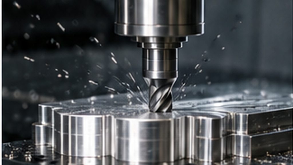
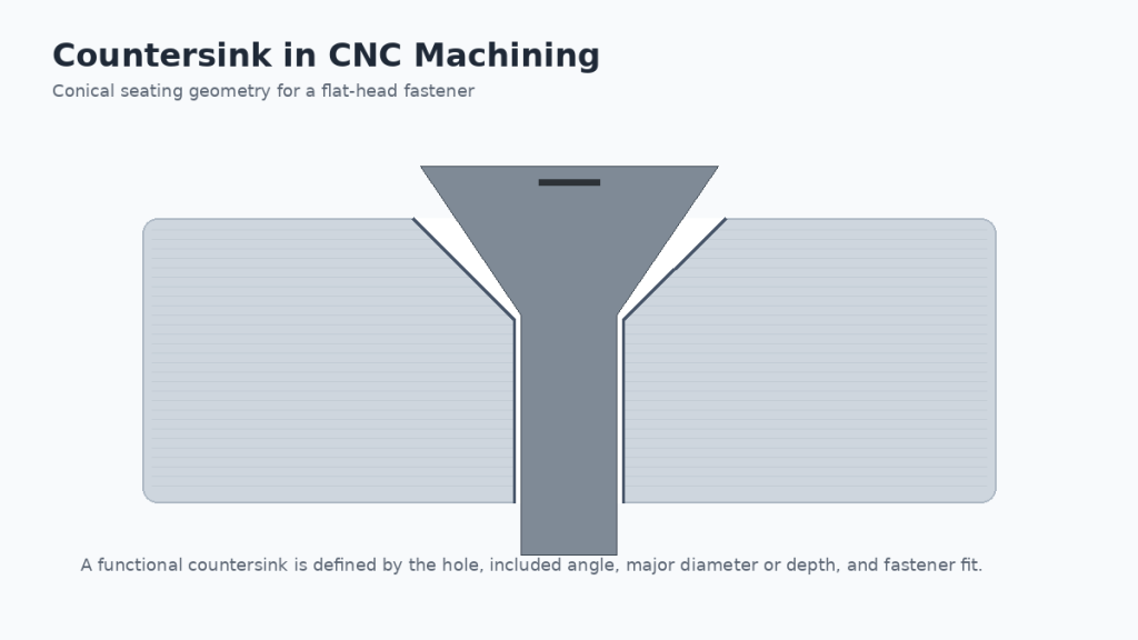
When a prototype must use a real engineering material, hold functional dimensions, or survive hands-on testing, CNC machining is often a practical bridge between a CAD concept and a production-ready part. It produces one-off and low-volume parts without injection-mold tooling, while preserving the material and surface characteristics that many design reviews require.
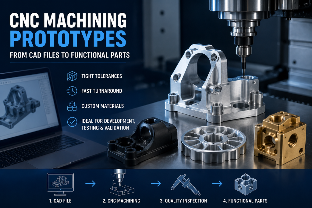
The right choice still depends on the part geometry, material, tolerance, quantity, surface requirements, and validation plan. This guide explains how to evaluate CNC machining for prototypes, what information to include in an RFQ, and how to move from a first part to a repeatable production process.
What Is CNC Prototype Machining?
CNC prototype machining is the production of a small number of parts directly from digital design files using computer-controlled milling, turning, or related subtractive processes. The machine removes material from a metal or plastic blank until the part reaches the programmed geometry.
Unlike a visual-only model, a machined prototype can use the same or a closely comparable material family intended for the finished product. That makes it useful for:
- fit and assembly checks;
- functional and load testing;
- thermal, chemical, or wear evaluation;
- ergonomic and cosmetic review;
- pilot builds before tooling or larger production.
The prototype does not automatically have the same cost, cycle time, or geometry as a mass-produced part. It is a validation step. The supplier should identify which features are representative of production and which are specific to the prototype process.
When Should You Choose CNC Machining for a Prototype?
CNC machining is a strong candidate when the prototype needs a real material, accurate interfaces, or a functional surface finish. It is especially useful when the design may still change and the cost or lead time of a mold would be premature.
Use the following decision guide rather than assuming that one process is always better.
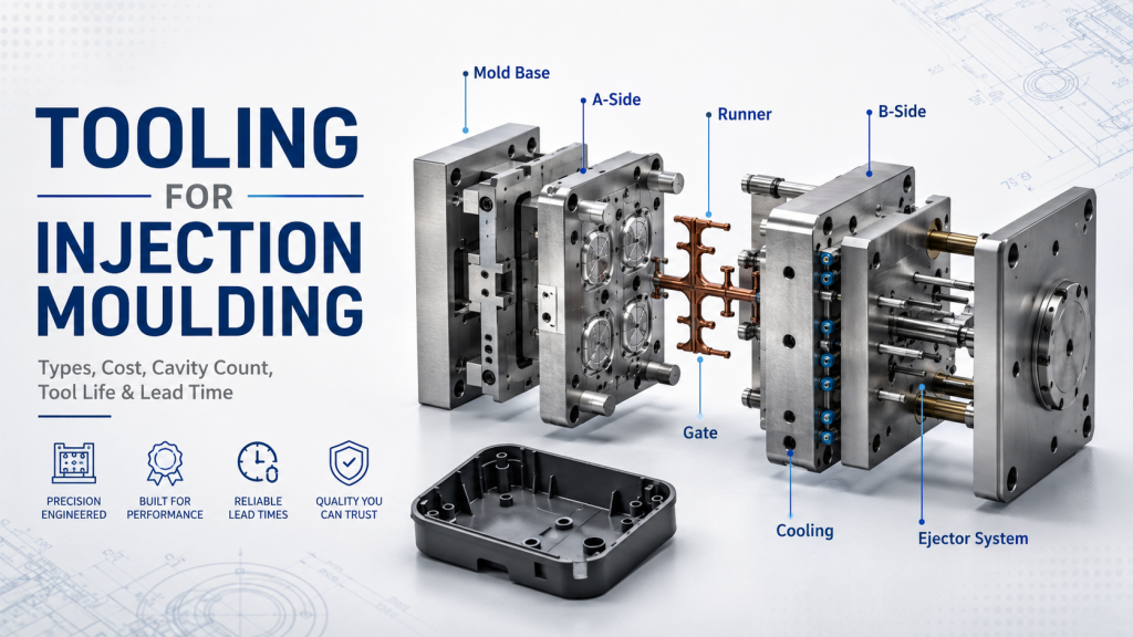
| Project requirement | CNC machining | 3D printing | Injection molding |
| Real metal prototype | Strong fit | Limited to selected metal processes | Usually requires tooling |
| Fast geometry iteration | Good for accessible features | Often very good | Slow and expensive after tool changes |
| Functional strength and finish | Strong when material and direction are suitable | Depends on material and build direction | Strong for the selected production resin |
| Complex internal geometry | Limited by tool access and fixturing | Often easier | Depends on core, slides, and draft |
| One or a few parts | Practical | Practical | Usually uneconomical |
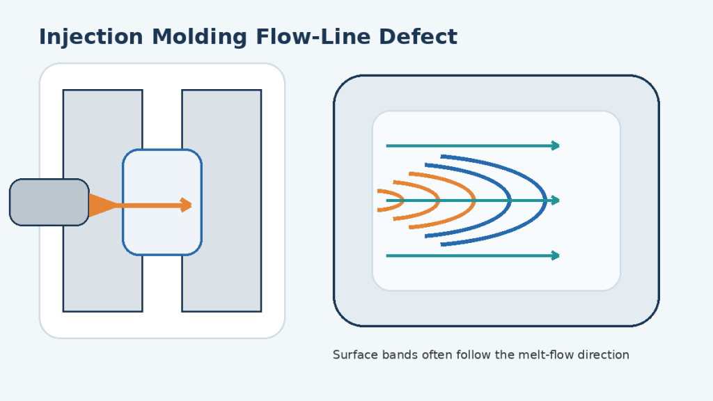
| Repeated production volumes | May work for low volume; review unit economics | Usually not the default for durable production parts | Often attractive after design freeze |
| Surface and dimensional validation | Useful for machined interfaces | May need post-processing | Useful when the production material and tool are available |
The correct choice depends on the validation question. If the team is checking a threaded metal interface, bearing fit, or machined sealing surface, CNC may provide more relevant evidence than a printed model. If the team is checking only an overall shape or internal airflow path, another process may be more efficient.
CNC Milling, Turning, and Machining Features
The manufacturing route should follow the part geometry.
CNC milling
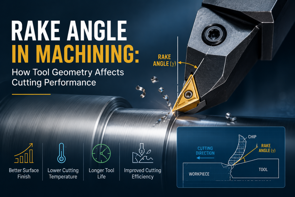
Milling is commonly used for housings, brackets, plates, fixtures, covers, and parts with prismatic or multi-sided features. The design review should consider:
- tool access to pockets, walls, and internal corners;
- required number of setups;
- workholding surfaces;
- deep cavities and thin walls;
- internal radii created by round cutting tools;
- holes, threads, and cross-drilled features.
CNC turning
Turning is suited to rotational parts such as shafts, bushings, pins, collars, and threaded components. A mill-turn process may be appropriate when the same part also needs cross-holes, flats, slots, or milled faces.
Multi-axis and special operations
Multi-axis machining can reduce setups for complex surfaces, but it is not a substitute for manufacturable geometry. The supplier should confirm the machine envelope, fixture strategy, access angles, and inspection datum scheme before quoting.
Other operations may be needed for a prototype, including drilling, tapping, deburring, grinding, EDM, or secondary finishing. List these requirements in the RFQ instead of assuming they are included.
From CAD Upload to a Tested Prototype
A reliable prototype program is more than sending a STEP file to a machine shop. The following workflow keeps design intent, manufacturability, and inspection aligned.
Upload the design package
Provide a 3D CAD file and, for parts with functional dimensions, a 2D drawing or annotated drawing view. The package should identify:
- material or approved alternatives;
- critical dimensions and datums;
- threads, inserts, and mating features;
- surface finish and cosmetic zones;
- quantity and target date;
- inspection or test requirements;
- packaging and confidentiality needs.
Complete a DFM review
The supplier should check tool access, wall thickness, deep features, internal radii, fixturing, burr risk, material availability, and inspection access. A useful DFM review explains the reason for each proposed change and separates mandatory changes from cost or lead-time suggestions.
Confirm material and finish
Material names alone are not enough. Confirm the grade, temper or condition where relevant, color, grain direction, heat treatment, and any required certificate. Surface finish should state whether the requirement is functional, cosmetic, corrosion-related, or simply a deburring expectation.
Quote and approve the build
The quote should make the assumptions visible: quantity, material, operations, inspection scope, finish, packaging, shipping, and revision level. If a tolerance or finish cannot be confirmed before production, it should be listed as an open item.
Machine, inspect, and report
The first article should be checked against the drawing and the agreed inspection plan. Depending on the feature, this may involve calipers, micrometers, gauges, a CMM, optical measurement, thread gauges, or a functional assembly check. The report should identify the measured feature, method, result, and revision used.
Feed the result back into the design
Prototype validation is valuable only when the result changes a decision. Record fit issues, tool marks, burrs, distortion, finish mismatch, assembly force, and test observations. Then update the CAD model, drawing, material, or process before the next build.
Materials and Surface Finishes
The material should be selected for the test the prototype must pass, not only for availability or appearance.
| Requirement | Selection questions |
| Strength or stiffness | What load, temperature, and direction will the part see? |
| Weight | Is a lighter alloy or plastic acceptable for the test? |
| Wear or friction | Does the interface need a specific hardness or low-friction behavior? |
| Corrosion or chemicals | Will the part see moisture, solvents, salts, or cleaning agents? |
| Appearance | Is the surface for a cosmetic review or a functional interface? |
| Production transition | Does the prototype material represent the intended production material? |
Common CNC prototype families include aluminum alloys, steels, stainless steels, copper alloys, engineering plastics, and other materials subject to supplier confirmation. The final page should list only grades Kemal can actually source and machine.
Surface options may include as-machined, deburring, bead or sand blasting, anodizing, plating, powder coating, painting, polishing, or other treatments. Every finish changes dimensions, appearance, or surface behavior to some degree. Mark critical interfaces and cosmetic zones separately.
Tolerances, Design Limits, and Cost Drivers
Avoid using a single blanket tolerance as a sales claim. Tolerance depends on material, feature size, geometry, machine strategy, setups, temperature, measurement method, and drawing datums.
For a useful quote, identify:
- critical dimensions and their functional reason;
- datum scheme and GD&T requirements;
- mating holes, shafts, seals, and threads;
- thin walls, deep cavities, and undercuts;
- cosmetic surfaces and acceptable tool marks;
- inspection documents required.
Prototype cost and lead time are normally influenced by:
- material and blank size;
- part volume and material removal;
- number of setups and special fixturing;
- tight tolerances or difficult inspection;
- deep pockets, thin walls, small tools, and complex features;
- quantity and repeatability requirements;
- surface treatment, heat treatment, and certification;
- packaging, shipping, and requested schedule.
The lowest unit price is not always the lowest project cost. A cheaper quote that omits inspection, finish, or a required setup can create another iteration and delay validation.
Prototype Case Study: Add Verified Evidence Before Publishing
This section should use one anonymized Kemal case rather than a generic success story. The minimum evidence fields are:
- application and part function;
- material grade and material condition;
- quantity and revision count;
- machining route and key features;
- critical tolerances and surface requirements;
- inspection method and report type;
- issue found during validation;
- corrective action and verified result.
If any field is confidential or unavailable, state that it is withheld or remove the section until the project owner confirms the wording. Do not invent a tolerance, lead time, defect rate, or customer outcome.
What to Include in a CNC Prototype RFQ
Send the following package to reduce quotation delays:
| Item | What to provide |
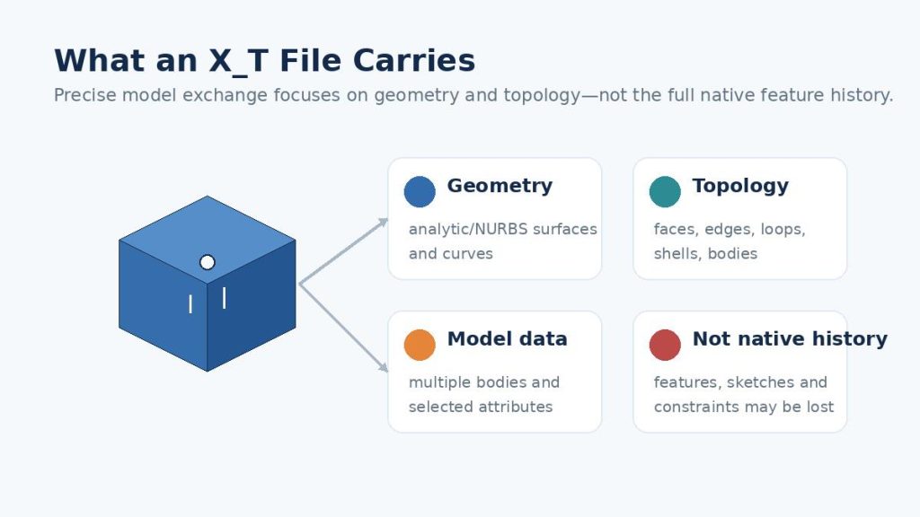
| 3D model | STEP, STP, Parasolid, or the supplier’s accepted format |
| 2D drawing | Datums, critical dimensions, threads, GD&T, and revision |
| Quantity | Prototype count and expected follow-up volume |
| Material | Grade, condition, approved alternatives, and certificates |
| Finish | Cosmetic, functional, corrosion, or coating requirement |
| Inspection | Critical features, report format, and sampling expectations |
| Use case | Fit check, functional test, thermal test, or customer demo |
| Schedule | Required ship date and any staged delivery need |
| Commercial details | Destination, packaging, confidentiality, and contact |
Frequently Asked Questions
Can I order only one CNC prototype?
Many CNC suppliers support one-off and low-volume work, but the practical minimum depends on setup, material, inspection, and finishing requirements. Ask for the complete project cost rather than assuming that a single part will have a simple unit price.
Do I need a 2D drawing?
For a simple geometry review, a 3D model may start the discussion. A 2D drawing is strongly recommended when dimensions, datums, threads, GD&T, finish, or inspection results are important.
How do I choose between CNC machining and 3D printing?
Start with the test requirement. Choose CNC when the prototype needs a relevant material, machined interface, functional strength, or representative surface. Choose 3D printing when the main goal is fast shape iteration or a geometry that is difficult to machine. A supplier can compare both when the design and test plan are available.
Can the prototype move into low-volume production?
It can, but the transition should be reviewed. The prototype may use different fixtures, toolpaths, inspection frequency, or finishing assumptions than a repeat production run. Treat the first parts as process-learning data, not automatic proof of production economics.
What affects CNC prototype cost and lead time?
Material, quantity, stock size, setups, geometry, tolerances, finish, inspection, packaging, and shipping are common drivers. A complete CAD and drawing package allows a more useful estimate.
Can inspection reports be provided?
The answer depends on the supplier’s equipment and quality process. State the required features and report type in the RFQ, and confirm whether the measurement method is suitable for the tolerance.
Start with a Prototype Review
The fastest way to evaluate a CNC machining prototype project is to share the CAD model, drawing, quantity, material, finish, test purpose, and target date. A qualified manufacturing review should return clear assumptions, DFM questions, inspection needs, and the next step toward a functional prototype.