Metal Prototyping Services
Metal prototypes for fit, function, and assembly validation
DFM feedback included · Optional dimensional / CMM inspection · Prototype-to-pilot support
Metal Prototype Manufacturing Capabilities
| Capabilities | Metal CNC Machining | Sheet Metal Prototyping | Metal 3D Printing Service |
|---|---|---|---|
|
Best for |
Tight-tolerance metal prototypes with defined datums and fit-critical interfaces |
Enclosures, brackets, panels, and formed assemblies where fast fit checks are the priority |
Complex geometry, internal features, lightweight structures, or part consolidation; critical interfaces can be post-machined |
|
Materials |
Aluminum · Stainless steel · Carbon steel · Brass · Copper · Titanium (as required) |
Aluminum · Stainless steel · Carbon steel · Galvanized steel |
Stainless steel · Titanium (material availability varies by process/partner) |
|
Typical tolerance |
±0.02–0.05 mm (feature-dependent; CTQ confirmed at quote) |
±0.1–0.3 mm (material/bend-dependent) |
±0.1–0.3 mm (as-printed); tighter on CTQ features via post-machining |
|
Typical wall thickness |
≥0.8–1.0 mm (material/feature-dependent) |
≥1.0–1.5 mm (material/bend-dependent) |
≥0.6–1.0 mm (process-dependent) |
|
Build size considerations |
Limited by machine travel and fixturing strategy; larger parts supported via multi-setup routing |
Limited by cut size and bend length; larger parts may require segmentation and welding |
Limited by build volume; larger parts may require split-and-join or post-machining strategy |
|
Surface / finish |
As-machined; bead blasting, anodizing, plating available |
Cut & deburred; powder coat or paint available |
As-printed; surface finishing and post-machining available |
|
Secondary operations |
Tapping · reaming · threaded inserts · deburr/chamfer · finishing as required |
Welding · PEM hardware insertion · basic sub-assembly support |
Post-machining on CTQ features · heat treatment (as required) · finishing |
|
Inspection options |
In-process checks · dimensional report · CMM (as required) |
Dimensional checks · assembly fit inspection (as required) |
Dimensional checks after post-processing · inspection report on request |
|
Typical lead time (business days) |
Standard: ~3–9 days · Expedited: case-by-case (eligible parts) |
Cut-only: ~2–4 days · With bending/welding: ~4–7 days (typical) |
Standard: ~5–10 days (incl. post-processing) · Expedited: case-by-case |
|
Cost drivers |
Material · setup/fixturing · machining time · inspection/reporting |
Cut length · bends · welding/hardware · finishing |
Build volume · supports · post-processing · post-machining/finishing |
Common Metal Prototypes We Build
Representative metal prototypes built for fit validation, functional testing, and pilot preparation.

Enclosures & Housings
CNC-machined or sheet-metal enclosures used to verify assembly fit, internal clearances, and mounting interfaces before pilot builds.
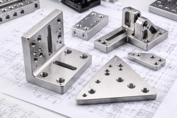
Brackets & Mounts
Precision brackets and mounts with hole location, slot alignment, and interface datums validated for repeatable assembly.

Heat Sinks & Thermal Plates
Machined thermal components with flatness-controlled surfaces for heat transfer testing and interface evaluation.

Fixtures & Checking Gauges
Workholding fixtures and checking gauges built to support repeatable builds, alignment control, and dimensional verification.

Covers & Panels
Covers and panels used to validate edge quality, hole alignment, cosmetic finish, and fastener fit.

Manifolds & Complex Blocks
Multi-axis machined blocks with ports, channels, and sealing features for pressure, flow, or functional testing.
Metal Rapid Prototyping Processes
Get metal prototypes built fast with Kemal’s in-house capabilities

Metal CNC Machining
Best for metal prototypes with tight tolerances, stable datums, and fit-critical interfaces. We use CNC machining to validate hole positions, sealing surfaces, and multi-face relationships. Dimensional or CMM inspection reports can be provided for CTQ verification.

Sheet Metal Prototyping
Ideal for enclosures, brackets, panels, and formed assemblies where fast fit checks matter. We support laser cutting, bending, welding, and PEM hardware insertion to validate mounting and assembly logic. Tolerances are reviewed based on thickness and bend geometry, with inspection support if required.
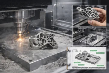
Metal 3D Printing Service
Used for prototypes with complex internal geometry, lightweight structures, or part consolidation that are difficult to machine. For functional builds, we often CNC-machine critical features after printing to meet CTQ requirements and inspection expectations.
FAQ's
What tolerances can you hold for metal prototypes?
For metal prototypes, achievable tolerance depends on the process, geometry, and how the part is fixtured—not a single blanket number.
For CNC-machined metal prototypes, most parts with stable datums and reasonable feature access are typically held in the ±0.02–0.05 mm (±0.001–0.002 in) range on fit-critical features. Tighter tolerances are possible on specific dimensions, but they need to be reviewed and confirmed at quote.
For sheet metal prototypes, tolerance is driven by material thickness, bend depth, and bend sequence. Flat features and hole locations are usually tighter than formed features, and we call out realistic bend tolerances during DFM review.
For metal 3D printed prototypes, as-built tolerances are looser due to the process. When critical interfaces are involved, we typically machine those features after printing to bring them back into tolerance.
In all cases, we review your drawing, identify CTQ features and datums, and confirm which dimensions will be controlled and how they’ll be measured. If required, we can support dimensional or CMM inspection reports so tolerances are verified, not assumed.
Do you support GD&T and CTQ feature control?
Yes. We support GD&T and CTQ feature control on metal prototype parts.
When you provide a drawing with GD&T, we review the datums, tolerance scheme, and CTQ features during quoting—not after machining. For each CTQ, we confirm how it will be produced, how it will be fixtured, and how it will be measured.
For parts with positional, profile, or multi-face requirements, we plan setups to protect datum relationships across operations. Where needed, we align the machining strategy and inspection method to the GD&T callouts rather than treating them as nominal dimensions.
We can also provide dimensional inspection or CMM reports for CTQ features so critical requirements are verified and repeatable across prototype iterations.
Which process should I use: CNC, sheet metal, or metal 3D printing?
It comes down to what you need to prove on the prototype—geometry, tolerance, or speed.
Choose CNC machining when you have tight datums, precise hole positions, sealing surfaces, threads, or mating features. If the part has CTQs tied to assembly fit, CNC is usually the most reliable route.
Choose sheet metal prototyping when the part is mainly bends, flanges, brackets, panels, or enclosures and you want a fast fit check. It’s also the right choice if you need PEM hardware, spot welds, or a realistic enclosure build early.
Choose metal 3D printing when the geometry is hard or impossible to machine—internal channels, lattice/lightweighting, part consolidation, or complex organic shapes. For functional prototypes, we often print the shape and then CNC-machine the critical interfaces so CTQ features still land in tolerance.
If you send the STEP + drawing and tell us what the CTQ features are (fit, seal, alignment, strength, weight), we’ll recommend the process that hits those requirements with the least risk and fastest path.
What inspection reports can you provide?
We can provide inspection reports based on what your prototype is meant to validate—fit, function, or release readiness.
For most metal prototype projects, we support basic dimensional inspection reports that verify key drawing dimensions and CTQ features using calibrated measuring equipment.
When tighter control or formal documentation is required, we can provide CMM inspection reports and first article–style dimensional reports (FAI) on request. These are aligned to your drawing, datums, and GD&T callouts, not a generic checklist.
If you have specific CTQs, we confirm which features will be inspected, the measurement method, and the report format during quoting, so the inspection output matches how the part will actually be used and evaluated.
Can you support fast-turn metal prototypes?
Yes. We support fast-turn metal prototypes, with lead time driven by process, part complexity, and material availability.
For CNC-machined metal prototypes, typical lead time is about 3–9 business days once the design is released. Simple geometries or single-setup parts can often be turned faster if needed.
For sheet metal prototypes, flat laser-cut parts and basic formed components can move quicker, especially when standard materials and finishes are used.
For metal 3D printed prototypes, lead time depends on build scheduling and post-processing. When critical features are required, additional time is planned for secondary CNC machining.
If turnaround is critical, tell us your target date and CTQ features when you request a quote. We’ll confirm what can be expedited and set a realistic build plan before starting.
Do you support secondary operations and finishing?
Yes. We support a range of secondary operations and finishing to deliver metal prototypes that are ready for testing or assembly.
Common secondary operations include deburring, chamfering, tapping, reaming, threaded inserts, and light assembly. For sheet metal prototypes, we also support PEM hardware insertion, welding, and basic sub-assemblies.
For surface finishing, options include as-machined, bead blasting, brushing, anodizing, plating, passivation, and laser marking, depending on material and application. For metal 3D printed parts, we can handle support removal, surface cleanup, and post-machining of critical features.
During quoting, we confirm which secondary steps are required and how they affect tolerance, appearance, and lead time, so the finished prototype matches your functional and validation needs.
What materials can you prototype in?
We prototype in a wide range of commonly used metals, with material selection matched to the process and the purpose of the prototype.
For CNC machining, typical materials include aluminum alloys, stainless steels, carbon steels, brass, copper, and titanium. These are commonly used for functional prototypes where strength, fit, or surface finish needs to match production intent.
For sheet metal prototypes, we regularly work with aluminum, stainless steel, and mild steel in standard thicknesses suitable for forming, welding, and hardware insertion.
For metal 3D printed prototypes, material options depend on the printing process and build availability, but commonly include stainless steel and aluminum alloys, with post-machining used when tighter tolerances are required.
If you’re unsure which material makes sense at the prototype stage, share the application, test requirements, and CTQ features, and we’ll recommend a material that supports validation without over-engineering the first build.
What do you need to quote a metal prototype project?
To quote a metal prototype accurately, we need enough information to understand function, CTQs, and delivery expectations—not just the geometry.
At a minimum, please provide:
3D CAD file (STEP or IGES) and 2D drawing (PDF) with tolerances and any GD&T
Material and finish requirements, including alloy/grade and surface condition
Quantity and target lead time, and whether multiple prototype iterations are expected
CTQ features, such as fit, alignment, sealing surfaces, or load-bearing areas
Inspection requirements, for example dimensional report, CMM, or FAI
If the part is part of an assembly, notes on mating components or functional testing are also helpful. With this information, we can confirm the right process, realistic tolerances, inspection approach, and a build plan before starting.

